|
This is due to the cable not being terminated correctly by either or both LAN adapter interfaces resulting in the cable "ringing". Other known causes are high drive levels of some LAN adapters which then overload the receive circuitry of the adapter it is connected to. The circuit shown below combats both these issues. It is nothing more than two 6dB (approx) attenuators (one for each leg or path). Attenuators exhibit two fundamental and valuable properties. They offer the cable a reasonable termination point as well as attenuating any reflections that may be present on the line.
If the problem is merely one of overloaded receive circuitry placing a 6dB attenuator in circuit reduces the voltage by 2 (power by 4). As the LAN specification calls for a transmit level of 2Vp-p and a receive sensitivity of greater than 350mVp-p the attenuator will not affect normal drive levels (6dB resulting in 1Vp-p in normal conditions). The attenuator now allows for a maximum of 4Vp-p before any overloading would occur. If ringing or reflections are the problem, usually caused by a bad termination at the receive end, the attenuator, being resistors, damps any oscillations appearing on the cable. Any reflections caused at the receive end are reduced by 6db before it reaches the transmitter. When reflected back they are again reduced by further 6dB thus our 6db attenuator offers a total 12dB attenuation on any reflections.
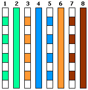
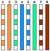
The using of this circuit has resulted in the stabilising of a number of problematic LAN connections and implementation is recommended after all normal possible faults have been eliminated (bad connectors etc). NOTE: Resistors are standard carbon film 1/8 watt or above and values are in ohms. Attenuators of other values or impedance can be calculated with the aid of the attenuator tables found at this webpage. The diagram to the right shows the numbering of a RJ45 connector (from the left with cable entry to the bottom, pins to the top and facing you).
1 - TX_D1+
© 22.05.01/15.08.05 |


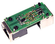
 These attenuators are easily built into CAT5 junction boxes (as can be seen alongside) or directly into a short LAN cable (ensuring no possible short reducing the reliability of the cable).

