Resistor Attenuator
Tables

Having to construct attenuators for a LAN problem (see 'A Real LAN twist cable') it was noticed that most attenuator tables are designed around 50 ohms. In today's world there are still many impedances used, 50 ohms for most industrial or mobile RF, 75 for most TV (video and RF), 100 for LAN, 600 for most balanced audio, etc.

It's all very well saying "divide by 50 and then multiply the result by the working impedance" but designing tables at what may appear an odd figure of 1 ohm the first mathematical stage is removed. This slight variation means you select the amount of attenuation you require and multiply the resistor values by your working impedance.


Attenuator Configurations

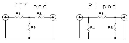
The 'T' and 'Pi' configurations, as shown below, are used for unbalanced (i.e. coax based) signals.

't' and 'pi' configurations

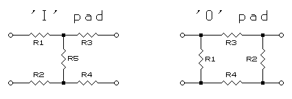
For balanced signals (using twisted pair or other balanced feeder) then either 'I' or 'O' configurations, as shown below, are used.

'i' and 'o' configurations

'I' is the balanced form of 'T' and 'O' the balanced form of 'Pi'.


Attenuator Tables

The tables below are designed for both unbalanced ('T' and 'Pi') and balanced ('I' and 'O') attenuators.

Please note the table is shown for 1W. Multiply the resistor values by the impedance of the circuit in which the attenuator is being used (e.g. 50, 75, 600W).


        T-Pad           Pi-Pad            I-Pad           O-Pad 
dB | R1,R2   R3   |  R1,R2   R3    |   R1-R4   R5   |  R1,R2  R3-R4 
___________________________________________________________________
 0   0.000                  0.000  |   0.000                  0.000
 1   0.058  8.667   17.391  0.115  |   0.029  8.667   17.391  0.058
 2   0.115  4.305    8.724  0.232  |   0.057  4.305    8.724  0.116
 3   0.171  2.839    5.848  0.352  |   0.085  2.839    5.848  0.176
 4   0.226  2.097    4.419  0.477  |   0.113  2.097    4.419  0.238
 5   0.280  1.645    3.570  0.608  |   0.140  1.645    3.570  0.304
 6   0.332  1.339    3.010  0.747  |   0.166  1.339    3.010  0.374
 7   0.382  1.116    2.615  0.896  |   0.191  1.116    2.615  0.448
 8   0.431  0.946    2.323  1.057  |   0.215  0.946    2.323  0.528
 9   0.476  0.812    2.100  1.232  |   0.238  0.812    2.100  0.616
10   0.519  0.703    1.925  1.423  |   0.260  0.703    1.925  0.712
11   0.560  0.612    1.785  1.633  |   0.280  0.612    1.785  0.817
12   0.598  0.536    1.671  1.865  |   0.299  0.536    1.671  0.932
13   0.634  0.471    1.577  2.121  |   0.317  0.471    1.577  1.061
14   0.667  0.416    1.499  2.406  |   0.334  0.416    1.499  1.203
15   0.698  0.367    1.433  2.723  |   0.349  0.367    1.433  1.361
16   0.726  0.325    1.377  3.076  |   0.363  0.325    1.377  1.538
17   0.752  0.288    1.329  3.469  |   0.376  0.288    1.329  1.735
18   0.776  0.256    1.288  3.909  |   0.388  0.256    1.288  1.954
19   0.798  0.227    1.253  4.400  |   0.399  0.227    1.253  2.200
20   0.818  0.202    1.222  4.950  |   0.409  0.202    1.222  2.475

Also included for download is an Excel Spreadsheet giving access to the formulae and allowing extension beyond 20dB. Simply enter the impedance in the blue block and the resistor values are automatically updated.


| | Ask a Question |

© 14.04.04