|
Before continuing, if the page on Earth Leakage has not yet been read, now would be a good time to divert attention for just a moment. Obviously, it goes without saying (although it is not that obvious to some judging by the emails I get) that leakage current is that which flows "during normal operating conditions". A current can be found to flow between the current carrying conductors and Earth during an earth fault. I continue with this toward the bottom of the page, but it would do good to understand a little more about leakage current first. Before we investigate the voltage-current relationship of leakage, a look at typical leakage. "If anything, it is doing you a favour! Now hereís what appears to be a controversial statement if ever there was one! The problem will be is that most will look at leakage currents, and then stop at that. There will be no consideration given to aspects and parameters of this current. Take the modern work desk. We covered this earlier, but suffice to say the modern desk has approximately 1mA of leakage current. At 230V that translates into 0.23VA (we need to talk in VA as this is AC). I have visited many offices where there is in excess of 100 desks, making this leakage at least 23VA.
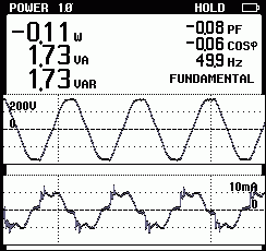
As power factor is the direct relationship between volt-amps and watts, and that watts is equal to the volt-amps multiplied by the power factor and thus the true energy consumed, we would land up (using our example above) with 23VA x 0 = 0. This means no pennies are unduly given to the electricity company. Actually, letís take this one step further. As the combined load is generally inductive, having a little capacitance will have power factor correction properties. This means the leakage, if anything, is actually lending a helping hand in ensuring the electricity company get less pennies and not more! But this also means that leakage currents cannot be ignored! Being capacitive means that any harmonic content is directly absorbed by the capacitors that exist between Live and Earth (not discounting that there are probably bigger ones across Live and Neutral). The absorbed harmonic energy is, however, of no use to man or beast apart from cleaning up the network a little (and if really bad can lead to nuisance tripping of earth leakage breakers). Leakage currents can become the reason Protective Earth systems can fail, but in this instance it is only the current that needs to be concentrated on, not the voltage of the supply. I covered the measurement of leakage in the previous chapter. Here I will show that the phase angle is a primary component of leakage that needs to be considered. This is probably one of the easiest methods of determining if there is a problem with Earth currents. Things are made a little more complicated in 3-phase systems, but most power is finally used in single-phase form making this true at the point of measurement. There is a need to split the difference between earth leakage and earth fault:
Current that flows, as described above, due to the physical characteristics of connected components when subjected to the applied voltage of a distribution network.
In other words; The wiring and devices fed from the distribution network will have capacitance with respect to local surround (i.e. Earth) and will, as a result of such capacitance, cause a current to flow when subjected to the applied Alternating Current voltage. e.g. capacitors in EMC filters.
Current that flows from the current carrying conductors to Earth through an unintented semi-conductive or conductive path.
In other words; Current that flows because there is a direct or indirect (usually resistive) path between the current carrying conductors and Earth when there should not be such a path and/or such a path was not designed. e.g. water across a terminal block. The difference is the first is accepting there are physical attributes of components used throughout a distribution network that will cause such a current, the second being current that is flowing because something has gone wrong. A phase angle of anything other than 90° will indicate a resistive and/or inductive component to the leakage and may well point to a load that has accidentally been strapped between Live and Earth instead of the proper L-N, or a short (or partial short) existing where it should not. Determining Fault Direction >>
© 14.09.06 |
 INTERPRETING THE READINGS:
 Most will look at the VA of leakage and immediately translate this to "pennies going down the drain". What is forgotten is that such leakage is primarily capacitive. A basic electronics fundamental principle is the current through a capacitor always leads the voltage by 90°. This will therefore give it a power factor of zero (or pretty close to zero!).