|
"Over-estimating spikes Spikes and transients both belong to the group of disturbances called "impulses". The difference between a spike and transient is, however, vital in the determining of impulse related issues. Before I continue; There appears to be a rather disturbing use of the word 'surge' to define an impulse. This, I believe, is directly attributable to impulse protection manufacturers as the word 'surge' is an emotive one (compared with 'transient' or 'impulse') thus making their marketing more effective! More about this here. The fact there exists a rather broad grey area between a spike and transient sure doesn't help to simplify the understanding between them! Spikes are very fast impulses, transients are slower ones and border on the area known as 'surges'. It's what defines 'fast' and 'slow' that causes the biggest complication. Added to this comes the words 'experience' and 'instinct' - now here's hoping a satisfactory explanation of what's been learned over years can be given! The best start is a revisit to the definitions. A Spike is a non-consequential (no damage) disturbance, although it is accepted it may cause communications disruption. A Transient is a consequential disturbance (component damage as a result, even if the damage is a weakening of the component). It is very easy to take these two definitions and interpret them to mean the damage is related to the amount of energy released. But this is incorrect! Although damage is related to energy absorbed by the vulnerable components, it is not related directly to the duration of the impulse. If this were the case life would be extremely easy!
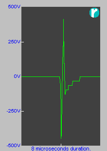
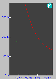
Above is an impulse that 'hit' an office complex when a set of fluorescent lamps were turned off. Also shown is the point where it was located on the CBEMA curve. If one were to use the curve then this impulse was non-consequential. It was! It did not even disturb the Local Area Network. The amount of energy released across the system must have been enormous in order to 'shake' the power in this way. If this same energy were released into a printed circuit board then it can be guaranteed there would have been component damage. Therefore what's been added to the equation to define which impulse category we're dealing with is 'location', specifically the location where the energy is absorbed. Location is effectively determined by the speed at which the component(s) will react to the impulse. As said earlier, if this were a high-speed, sensitive type circuit then damage is a near certainty. However, it was on the mains and most electronic equipment will have filters on the mains input. The inductors within these filters would simply absorb the change, and passive appliances (fridges etc) that have no protection would simply react in the same way. But, we've just said the energy is absorbed by inductors yet no mention of damage. What effectively needs to be considered is where the energy will dissipate, and dissipate as heat. If there is a chance it can damage then there is a reason to consider the impulse as a transient. Fortunately very high speed transients are generally lost in mains wiring simply because of the impedance of the wire itself, never mind the fact most breakers are coils, etc. This is the reason most impulses with a total duration below 10µs are regarded as spikes as they have little chance of the energy being propagated. By the time impulses reach the audio spectrum (20kHz) then things start to change dramatically. It is generally accepted that impulses with a half-cycle time of 50µs or longer are well within the transient range. So, between a total duration of 10µs and half-cycle times of greater than 50µs is the grey area we were referring to earlier. But then comes the level of the impulse, this being the final factor in the equation. What constitutes a high level is again a contentious issue. What can be safely stated is; anything that exceeds the breakdown of any component falls into the realm of transient. By breakdown we refer to a voltage that when exceeded causes a current to flow between two otherwise isolated parts of a component or device. This breakdown can vary purely in the design of equipment. Normal wiring is quite capable of accepting impulses of 25µs at 2kV. However, pop a 350V gas discharge tube across the mains and an impulse of only a few hundred volts could cause the gas discharge tube to fire with what might be dire consequences (hopefully nothing more than popping a fuse and powering down the equipment). Just when we thought the grey area of spikes and transients had been made a bit more black and white, some guy comes along and adds another factor to the equation - the design of the gear! Told you, this is very much a field of 'instinct' and 'experience' - but this does not make your life easy. Sorry, but there is just nothing that can be done about it. What can be said is the difference between a spike and a transient is dependent on the susceptibility of the device subjected to the impulse - in other words, back to square one! Not really. In our next section we investigate curves of what is accepted by industry as damaging and non-damaging impulses. These are known as the CBEMA and ITIC curves. It must, however, be remembered that these are still only guidelines as thought out by a bunch of designers as to where their equipment may be damaged by impulses. Not every designer will think of designing with these curves in mind! Although it was stated that things become interesting from 20kHz and lower, the same can be said of above 20kHz. Although the energy propagated above 20kHz (50µs) falls dramatically as the frequency rises, another interesting factor starts to arise. Resonance exists at every frequency, but at lower frequencies it takes definitive components of inductance and capacitance at correct values to achieve resonance on a frequency. At high frequencies this rule does not change, but the components can be replaced by the inductance of the wire and simple components e.g. electromagnetic circuit breakers. The capacitance is found between the wire and its surroundings. The fact such resonance may exist is not the real issue, until there is something that causes such resonance to be excited. The usual excitation will come from extremely sharp changes in voltage from things such as loads (especially inductive) being switched, lightning strikes, etc. As said earlier, subjecting an imperfect source to a non-linear load gives rise to harmonic content. What is forgotten by many installers of lightning protection devices is the very devices they install are deliberately non-linear (not to conduct until a threshold voltage is reached). If, at 50Hz, 3rd and 5th harmonics are predominant with hi-tech loads then there is nothing to say this cannot happen at many kHz. What is also not well known is that resonance can occur in nodes along a length of wire, much like a violin or guitar string made to oscillate at an octave rather than its base note. Getting a string to oscillate like this is achieved by creating a dampened point. A lightning protection device is exactly that, a dampening point.
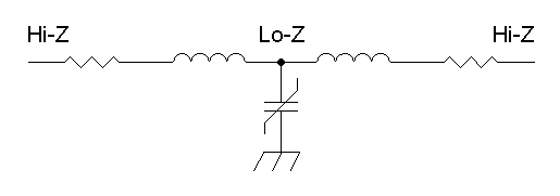
We need to visit the rules of RF in order to show what occurs here. The node is formed by "impedance transformation" (impedance change) with the aid of inductance and capacitance. MOV based lightning protection modules have a high capacitance so having the central component is easily achieved. The conductors' main characteristic is not the resistance everyone loves carrying on about, but inductance. We therefore, very easily, achieve the circuit above. By installing the lightning protection in just the right spot (and, knowing Murphy, this will occur with no difficulty at all!) we will create a situation where any impulse centred on the correct frequency will find its way right through the installation - right past the protection! This very scenario has had some engineers believe impulse protection devices (their proper name) do not work claiming they have "high let-through voltages". Although let-through voltages are real, they are in no way as high as claimed by some. In most instances it is this scenario that leads them to believe the exceedingly high voltages exist (for more info, see here). To add insult to injury, it has also been heard from the mouths of so-called lightning experts that their protection will stop all transients faster than 50µs (above the audio range) and therefore, based on this, monitoring of high speed transients is unnecessary. This is a very dangerous statement! A 90µs pulse may well be recorded and may well be clamped, but nothing is known of the 3rd harmonic (30µs) and 5th harmonic (18µs) pulses, to name only two. And then there is another seldom traced fault associated with high-speed, high-voltage spikes - they can lead to what could be interpreted as breakdown within a circuit. As shown above, the power circuit some way into the installation may become a high impedance and therefore have a high voltage impulse existing causing insulation breakdown leading to a high current demand. When tracing the source of a problem, we've proved that the relationship of the voltage vs. current is important. When using inferior instruments (low sampling rates), the waveform capture could easily show this high current leading to a sag in voltage. This could cause the user to deduce that the fault is internal to the site, when in actual fact the problem is an external one. The power wielded in a transient may not be excessively high because the time duration is extremely short, however, should the voltage reach breakdown point then an ionised path is created allowing serious current to flow (e.g. from Phase to Earth). The 'damaging' energy is therefore not the transient which causes the breakdown, but the power available across the two points that can now flow because of the created ionised path. If impulses are suspected of causing communications difficulties (or knowing they do and there is a desire to know when they 'hit'), or there is a suspicion they are the cause of a significant breakdown, then having recorders capable of capturing such impulses with a resolution of 1µs or smaller (as well as displaying the impulse itself as "recognising signatures" demonstrates), and plotting them on a recognised curve such as the CBEMA, is of utmost importance. We investigate this curve. Understanding the CBEMA Curve >>
© 09.07.04 |
 INTERPRETING THE READINGS:

