|
Impulse protection devices are wonderful for saving a pricey piece of equipment being damaged by a transient down the line, or even an over voltage if the protection is correctly installed. I need to clear up something first. There appears to be a rather disturbing use of the word 'surge' to define an impulse. This, I believe, is directly attributable to impulse protection manufacturers as the word 'surge' is an emotive one (compared with 'transient' or 'impulse') thus making their marketing more effective! The true definition of a 'surge' is the increase in RMS voltage over a half-cycle or longer without a distinct distortion in the waveform (and had the exact same meaning as 'swell', the choice purely depended on which area of the world you were in). The repetitive banging on of manufacturers of lightning protection with their definition of a surge has managed to even get the most correct of engineers to accept the more layman definition being simply a significant increase in voltage (sometimes even forgetting the RMS part!), and with no regard to the duration of the increased voltage.
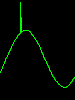
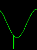
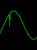
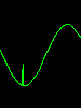
First, some facts. Impulses can be additive, subtractive, and oscillatory. Additive being the impulse increases the absolute RMS of any half cycle (as is seen in the two left-hand captures below). Subtractive being the impulse decreases the absolute RMS of any half cycle (as shown in the centre below). | ||
  Additive |
  Subtractive |
 Oscillatory |
And, finally, oscillatory where the RMS is not affected as the impulse has equal positive and negative portions and is a short burst of high frequency superimposed on the fundamental waveform (as seen above right). And now we apply these facts. Manufacturers of 'surge protection devices' (SPDs) claim to limit the voltage that will enter the protected system i.e. ensure the peak voltage remains below a pre-set limit e.g. 375V on a 230VAC input (which, remember, reaches 325V peak). Based on this, the SPD will only function with the additive impulse, and not with the subtractive and oscillatory type impulses (where the SPD clamp voltage is not exceeded). Yet the term 'surge protection' does give one the impression the device is able to protect the equipment against the onslaught from any impulse! The typical SPDs (featured below) will not cope with a true surge i.e. swell. In these situations they tend to self destruct thus leaving the devices they were intended to protect totally unprotected against any form of over-voltage, including transientary! Subtractive and oscillatory impulses can be as damaging to vulnerable equipment. By using the term 'surge', SPD manufacturers have clearly indicated to the knowledgeable engineer they are only doing a portion of the protection required, as opposed to their marketing which claims they are offering 'complete' protection! So even if an SPD is in full working order, it does not protect a device against all forms of impulse damage. As much as I despise the term 'TVSS', it is probably the best description of the limited capability of SPDs. Broken down; A Transient (short duration - microseconds), Voltage-Surge (significant increase in voltage), is Suppressed (brought under control). Do note how the term 'surge' has had to be clarified to fit in with the marketing material by referring to it as 'transient' (short term), in other words not a real surge! Impulse protection is a more accurate term as it clearly indicates that the transition towards the high voltage is brief. However, true impulse protection devices (catering for all forms of impulses shown) are far more complicated than simply using voltage clamping. By banging on about 'surge protection', SPD manufacturers have unwittingly admitted they only do half the job. I have seen one brochure where they state, quite clearly, that "the sole function of a surge suppressor is to limit transient overvoltages to [attempt to] protect sensitive electronic equipment". Hmm, I see this as a case of having 'shot themselves in the foot'. Yippee! That'll teach them for messing about with terminology! Ok then; If we accept (for a moment) that 'surge' is a simple reference to additive impulses i.e. transient overvoltages, then we can investigate the two basic types of 'surge' protection and their method of operation (which varies slightly between the two).
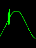
The first, more common type of protection uses devices known as Metal Oxide Varistors, or MOV for short. It simply comprises of two plates separated by a substrate that starts to conduct once a "breakdown" voltage is reached. The beauty of these devices is that once the offending voltage is removed they stop conducting i.e. the offending voltage is merely limited or "clamped" at some pre-set value as determined by the MOV's substrate. However, the voltage at which this clamping takes place is not a sharply defined point and is largely dependent on the current behind the offending impulse. The voltage marked on the MOV is the voltage at which current starts flowing through the MOV, see the accompanying graph. What some designers are prone to do is fit lower voltage devices in order to take advantage of a lower clamp voltage. It is not uncommon to find 275V MOVs in a 230VAC protection device. During normal operation where the peak voltage is 325V the MOV may only (apparently) conduct a few mA. However, the designer has not taken into account that for every mA of current the MOV is dissipating ¼-watt of instantaneous heat. The current curve, however, is non-linear with the MOV only conducting at or around the peak of the wave. The average dissipation will therefore be a lot lower than ¼-watt which gives designers a false sense of security. The MOV material works in two ways, first the average power it needs to dissipate as well as instantaneous current flowing through it. The latter easily being exceeded without much heat being generated. As there is no headroom all transients, including non harmful ones, are clamped and these, together with the warming of the MOV through the current drawn, starts to break down the material (literally forming holes through it). Breakdown curves such as the accompanying picture are highly likely when damaged parts of the material "flash over". Note how just after the voltage was clamped the MOV stopped conducting as the floor voltage was reached. If the underrated MOV manages to remain undamaged it is, due to the non linear current curve, likely to increase the harmonic content of the overall current curve of the installation it is protecting, the equipment itself probably being a piece of hi-tech i.e. a switch mode PSU, thus adding to the reduction of the power quality as a whole. If sufficient number of protection units are used this could become a substantial figure.
MOVs do have a small problem in that when they absorb a transient, the material within them starts to break down permanently. Over time they start conducting under 'rest' conditions and begin getting warm. And, when they 'hot up', they start conducting even more making them even warmer. When this mode occurs it can be seen the MOV suffers thermal runaway and burns itself out (literally). I must admit that I am a little concerned with a new type making its way on to the market. Realizing this flaw in MOVs, a company has begun making a MOV with a thermal cut-out (much along the same lines as the old thermal cut-out on transformers). Sounds like a wonderful idea, until one investigates this fully. When the MOV is new and in a pristine state, it draws no current. When failed (the thermal cut-out having operated) the MOV again draws no current. My simple question of how does one know that the protection has failed, has never been answered! I think this one needs to go back to the drawing board and a 3-leg version be created allowing the designer to detect if the cut-out has fulfilled its purpose.
Although extremely successful in data circuits, gas discharge tubes are only truly suitably in mains situations where the incoming current, and especially the fault current, can be limited. The reason being these devices will attempt to clamp by "shorting out" the incoming supply. Should the transient happen on the upward slope of a cycle the tube will continue conducting until the voltage reaches almost zero on the downward slope. There is a situation that can occur where the turn on speed of the gas discharge device is so fast the circuit it is connected to enhances the discharge waveform such that no further current flows through the discharge device and it extinguishes. This effect, known as "commutating effect" happens as a result of dampened oscillations on the circuit which are excited by the discharge. These situations are, however, rare even though this effect is relied on by protection device engineers. Because of this inability of the gas discharge tube to extinguish before the "zero crossing" will usually result in either the appliance's fuse blowing or a breaker tripping. This makes them totally unsuitable for use in remote locations where it is possible that they be triggered. I speak from experience having had an appliance fitted with these and the fuse was having to be replaced, regularly! A further problem, not commonly known, is that gas discharge devices become 'leaky' when having absorbed energy during a transient. The extent is dependent only on the type of gas used and the level of the transient. The gas, during the conduction phase, is superheated and deposits the solid form of the gas on the inner of the casing of the tube. If mercury vapour then mercury is deposited. Even if the gas does not deposit on the inner of the device, the gas itself depletes with each and every transient (and current conducted during the cycle) and, over time, the strike voltage of the tube increases to a point where the spacing between the contacts determines the strike voltage (which could become may kilovolts!). A further complication is the contacts could start to melt with the current and, if hot enough, vaporise. The vapour then depositing on the casing causing the same effect as with the gas. If sufficient metal is deposited it starts to conduct or, worse still, appears to yield sufficient insulation resistance but then breaks down long before reaching the marked strike voltage. Gas discharge protection units should be clearly marked so that decent current limiting (breaking) devices are used to remove the "sustaining" voltage when the discharge tube strikes. If the issue is nuisance tripping, you would do well to seek out any possibly failing protection units. Gas discharge tubes have their place in power - we'll show this later in the Solutions section - but not from Live to Earth or Neutral. Personally, if I see a gas discharge tube from Live to either Earth or Neutral, then out comes the cutters and one tube is removed! It is then replaced with a more suitable MOV.
© 29.11.03 / 06.05.05 |
||
 Culprits:
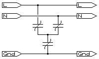 Alongside is a diagram of a well proven design of MOV protection. Each MOV is a minimum of one-half the peak of the incoming voltage. In this design voltages between each connection can be no more than twice the MOV voltage as well as the MOVs share the impulse energy being dissipated. A 185V MOV would do nicely for typical 240VAC input equipment, allowing for voltages up to 260V input.