|
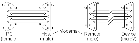
In the paper "Using PC RS232 Ports" we covered the basics of connecting to a PC com port. When using modems (including radio modems) to remotely connect to a device connecting the devices to the modem usually poses a problem. Connecting the PC to the 'host' modem (that which is at the main PC end) is best done with a 'one-to-one' cable i.e. pin 1 to pin 1 etc. and usually does not pose any problems. The main difficulty is is knowing what pins to swap at the remote (device) end.
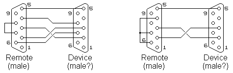
This difficulty is owing to the fact most devices that are intended to be connected to a PC have internal wiring such that the pins are 'ready' for connection directly to a PC com port via a com port extension cable. As the modems have the same type of internal wiring using a 'one-to-one' cable will result in the two Transmit Data pins being connected to each other, likewise the two Receive Data pins, and so on. The result being that no data can pass between the remote modem and the remote device. In order to accomplish data and control signal transfer certain lines need to be 'crossed over' as shown in the example above. Not all devices have all the required control signals and not all modems have settings allowing the control signals to be ignored and when this combination is used the only method to have the modem work satisfactorily is to 'jumper' or link some of the signals fooling the modem into believing all is ok. Below are two twist combinations, the first when the remote device has only RTS and CTS lines and when no control lines are provided by the remote device.
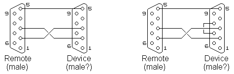
It will be noticed the 'source pin' i.e. the pin used to hold the input pins high, changes in the two examples. This is as a result of the control signals being used in the left situation causing the DTR to drop on the modem, this usually being an instruction to disconnect. In the situation to the right, where no control signals are used, the likelihood of the DSR signal dropping is low thus making it a more stable pin for use as a 'source pin'. Unfortunately these diagrams can only be used as a guide as there are many "modems" (especially radio modems) that use the various control signals in their own manner and might require different wiring to what is indicated above. As a recommendation it is always best to start with the basic wiring, as indicated on the left below, and to program the modem such that it ignores all control signals. Only if data flow is corrupted (either the modem or the device cannot operate at the speed required) should control signals be used.
The only unusual situation is when the remote device has been designed for a RS485 converter, in this instance it would require the RTS and CTS pins to be bridged fooling the device into believing such a converter is in place (as shown above right).
© 04.10.00 |