|
The following was drawn up in response to a request for a signal amplifier to take 0-60mV signals found across current shunts on a wind-solar system and present them as 0-2.4V signals into a data logger. The logger in question uses a common negative for all 8 inputs which meant:
To overcome the first problem the obvious solution is to use a balanced input amplifier and this can be seen in the circuit below. The second problem is tackled by creating an input reference point that is tied to the output thus compensating for any errors that may exist when feeding the logger some distance from the shunts. Before we delve into the circuit itself we'll digress onto the design philosophy adopted in this instance. Although many op-amps are available that could work rail-to-rail, both on the input and output, they may not be available to everyone wishing to build this circuit either through location or a wish to use what's in the 'junk box'. With this in mind, thought was given to a circuit that would use any commonly available dual 8-pin op-amp e.g. TL082 (a personal favourite), LM358, etc. The TL082 has a better frequency response and slew rate on the output as well as a much lower cross-over distortion figure as well as using less current. All of these devices require some form of negative rail supply. The reason for this is the output transistors within the op-amp cannot pull the output completely to 0 volts which would mean that with no input present you would be led to believe there was a slight output from what was being monitored. By pulling the -VE supply to the op-amp negative by only a few volts (usually 2V would suffice) the transistor will have sufficient "headroom" to bring the output to zero volts when required. It is usual practice to leave a little more room for manoeuvring in the event the output has to go a bit negative, thus would happen if the logger's common was slightly negative to the amplifier's ground. As this circuit was to get it's supply from a single voltage source, e.g. 12V battery, a negative voltage generator is incorporated and as this is easily achieved with only a handful of readily available parts, and with the ease of construction maintained, it was deemed worthwhile.
The amplification of the amp is fixed at 40, this is achieved with the 39k feedback and the negative input 1k resistors. It is advised, if possible, to select these resistors by hand using a very accurate multimeter. The cost of a string of 1% metal film resistors in order to find a reasonably accurate valued one is still by far more economical than obtaining high accuracy types. Achieving balance is accomplished with the preset. The combination of the 47k parallelled with the 220k and 20k preset (set approx midway at 10k) is very close to 39k, the result being a balanced input presented to the op-amp. The ground reference is achieved by the addition of the 22 ohm resistor (value not too critical, just keep under 50 ohms) in the positive input circuit. Should the ground of the logger (or other instrument) be at a voltage other than the ground of the input amp, the output automatically compensates for this and the offset thus minimised. Noise across the input of the logger will also be reduced by this arrangement.
It is possible to dispense with the preset and 220k and replace the 47k with a 39k resistor. If this is the desired route it is advised to first match as closely as possible a pair of 1k resistors for the input and a pair of 39k resistors for the ground and feedback. As soldering can cause these resistors to change value, use an 8-pin mil spec IC socket to house the resistors. This alleviates the need to solder as well as the ability to easily change while trying to achieve best balance or changing of gain if required.
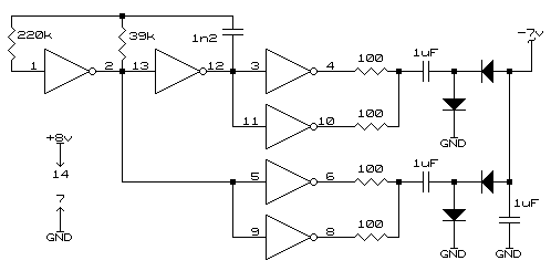
The reason the output from the negative supply is slightly lower than the positive supply voltage (8V) is the voltage drop on the output diodes and also a little loss on the IC itself. -7V is a round figure but depending on the load drawn it could be as low as -6.5V. Although not as efficient as a switch mode supply the design, like the signal amp, has been done with thoughts of simplicity and more readily available parts.
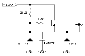
The voltage of this supply is not too critical and may be from 7 to 10 volts. The junk-box alternative of a simple zener diode and emitter follower regulator is also acceptable. The only criteria being the NPN transistor having a working voltage that exceeds the possible surges that may be expected on the supply.
One component often not seen on power supply circuits is the output protection zener, in this case a 10V. This ensures that should the supply regulator fail the only damage will be the input fuse and the regulator and possibly the protection zener. The amp and negative rail supply being left unharmed.
© 16.02.01 |

 Using a dual op-amp (pin numbers of the second amp shown alongside), two such channels can be constructed for measuring as an example the currents from the wind charger and solar panels independently. Using a TL084 device (quad op-amp) would allow four such amps to be built using the minimum of space.

