|
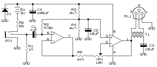
The following was built when having to interface a 12-string guitar to a studio audio mixer. The guitar was fitted with a piezo bridge pickup needing a high impedance input (greater than 250k) but standard mixer inputs vary between 5 and 20k. Also, the guitar is unbalanced with the mixer offering a balanced input, the latter being more desirable as noise is reduced. The amp shown below is split into two sections, the first offering a relatively constant impedance input with the second section being nothing more than a reasonable driver for the output transformer.
Although a balanced output could be created by having the second op-amp act as an inverter and the output taken from both op-amp outputs, it was decided to make use of a transformer to overcome three typical problems associated with electrically coupled outputs. By coupling to the op-amps:
With a transformer all the above issues are solved. There is no low impedance ground reference for RF to follow, DC blocking capacitor breakdown is eliminated, and the amp will still deliver the same amount of signal with no adverse effects if one output leg is at ground (when fed into an unbalanced input). Choosing the transformer is fairly critical so as to achieve a reasonable amount of audio bandwidth. 600 Ohm "line signal transformers" as used in the comms industry are not suitable as they are usually designed to pass audio in the "telephonic" range of 300-3400Hz only. There are more suitable audio line transformers available for this type of work and should be sought for this application. The frequency range required is approximately 50-8000Hz, anything beyond is merely a bonus. Also, ensure the isolation is better than 100V so as to ensure no cracks from winding-to-winding breakdown when phantom power (usually about 50V) is on the mixer input. Some mixers cannot have the phantom power applied to only selected channels but work on an "all or nothing" basis meaning phantom power may be on channels not requiring it, this must be catered for. THE POWER SECTION: The first option is simply a dry cell. R6 limits the currect when C4 is fully discharged. The second option is for using a rechargable battery, although there are many who still do not favour them. Rechargable batteries have improved dramatically over the years, especially as many types are available with limited or none of the problematic 'memory' effect. A majority of these are also capable of being charged at a continuous C/10 without damage, making the charger and charging exceedingly simple (plug in overnight and it's ready the next morning). R6 serves two purposes, the first is as a current limit when the unit is powered up, the second is as the current limit for charging. D1 stops current flowing through the circuit when the battery is being charged. The charge voltage, approx -10V, is placed between the ring contact and ground (using a stereo plug as opposed to a normal mono plug). Ensure the current during the charge cycle never exceeds 1-tenth the capacity of the battery.
© 03.05.01 |
