|
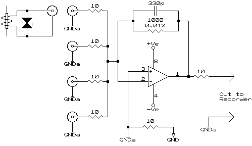
There are times when the currents from separate power distribution points need to be summed in order to read the total current being drawn from a supply. This could be achieved by monitoring separate points either through the same recorder, or worse still, two separate recorders. In both cases the results need to be artificially summed to get the total current draw. Two problems exist with this, the first being the actual VA, VAR, kW, etc cannot be measured as "inter distribution point" currents are not taken into account. The ideal solution would be to have the selected distribution points all supplied from one common supply, or at least all the required phases available for common clamping in one CT in order to affect measurement. This is not always practical. Wiring CTs in series, each CT with it's own termination resistor, will only apply if the input to the recorder is greater than 1000 times the sum of all the termination resistors, this is usually an impractical figure. Wiring in parallel requires that the recorder has a near zero resistance input, this not being the norm as most fix-on or clamp-on CTs output a voltage relative to the measured current. Wiring either in series or parallel also creates a further complication if certain CTs need to be taken out of circuit. Choosing the correct CT and using the circuit below both problems mentioned above are eliminated.
Circuit Description The circuit will be well known to audio buffs (specifically audio mixer designers) as it is typically used as a mixer bus amplifier as, owing to the fact the summation input is effectively a "zero ohms" point, it offers the best inter-input isolation i.e. input 1 is not affected by anything introduced on input 2 as well as each input is a constant impedance being the input resistor. In our case this allows individual CTs to be disconnected as required, with no effect on the remaining devices connected. The 10 ohm resistors and 330pF capacitor are EMC protection components and do not affect the accuracy of the summing circuit. The only factor to be borne in mind is the output is inverted in phase to the input, this is counteracted by reversing the CTs on installation.
In our example using the 1:2000 ratio would result in 1mA on the input for every 2A measured, or 2.5mA for 5A (the full scale of the smallest available CT). This would result in an output of 1V and 2.5V respectively. By choosing the correct ratio and feedback resistor the desired range can be achieved. It is not advisable to have a feedback resistor of lower than 500Ω or greater than 5kΩ. And then came practice There were some surprising results. We had a slight phase shift (expected) which was leading in phase (unexpected - remember, we're dealing with inductors) but this increased with using the CT in the usual "current to voltage" mode (very unexpected). Quickly explained, this is the mode when a resistor is placed in parallel with the secondary and the voltage generated across the resistor is measured and taken as the current. Our results showed the higher the value of the resistor the worse the phase error. This seemed to prove the use of the current to voltage convertor shown above i.e. to feed the CT into zero ohms, is the proper way to interface to a CT. To add further backing to this statement, by feeding the CT into a 'dead short' there is almost no chance the CT can saturate as can occur with a resistor across the secondary. The saturation occurs as there is a transfer of power from the primary (single turn) to the secondary and into the resistor. Should the amount of power being transferred exceed the amount 'deliverable' by the core it will saturate. At the end of the day we found the circuit coupled to the CTs supplied by Sentran exhibited an accuracy of 0.1% at 50Hz and better than 0.5% at 5000Hz (attributed to the 330pF cap in the feedback path). Also, a 1.25 degree leading phase error at 50Hz which disappeared (i.e. 0 phase error) at 200Hz through to 5000Hz i.e. an ability to measure to the 100th harmonic accurately.
A further application of this circuit is for measuring leakage currents where it is not possible to physically bring the conductors together through one low current CT. The CTs need to be tested for best match. If absolute accuracy is required, especially if the circuit is being used for leakage detection, then slight CT imbalances can be nulled out using a 4.7Ω for R1 and 10Ω presets in place of R2..R4. Setting Up: Operation:
© 04.11.01 |
 Choosing the CT