|
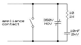
Almost everyone knows what it sounds like. It always makes itself known during the quietest moment of a talk being given. It either comes across as an annoying little click or a deafening crack, maybe somewhere in between. Yes, it's the interference heard through a public address when an electrical appliance is turned on or off. It would be nice to blame this one on Marconi as he was the inventor of the spark generator, wasn't he? Whatever the case, this is the principle of the interference being a spark gap, created when a contact is closed or opened. Usually, to create a spark generator one needs an inductor to resonate. With an electric motor or florescent tube it is provided within the design but this does not answer why tea urns are renowned for creating such disturbances. What is not generally known is that the building wiring is the inductor, the pair of wires (N & L) forming a resonant length much like a ¼-wave cavity or lecher wires. During a contact closure the oscillation is usually damped but when the contact opens the appliance end of the wiring becomes a high impedance. This allows the voltage to fluctuate dramatically and as this is the high impedance end the opposite side, the point at where the wiring terminates in the building wiring, is the low impedance end and therefore the high current side. During the oscillation very high levels of current can be found to flow at the low impedance point and the results seen throughout the wiring. The cure is fairly simple, dampen the oscillations. This can usually be achieved with nothing more than a capacitor and resistor in series, the combination then wired across the contact as shown in the diagram below.
Care must be exercised in the choosing of the components. It must be remembered that even though the components are going to suppress the oscillation they are also going to be subjected to the sharp voltage rises and falls, and thus high currents, as the contact opens and closes. Not only are the components subject to the currents involved with the device they are suppressing, but any spikes and transients found on the mains wiring. With the above in mind it is advised that the power requirements of the components not be skimped on. It is strongly recommended that the capacitor and MOV be about 15-20mm in size for no other reason other than they have the surface area to dissipate any heat generated during the suppression of spikes and transients. The resistor should no smaller than 1 watt and carbon or metal film. Wire-wound resistors are in themselves inductors and tend to aggravate the problem rather than eliminate it. A further advantage with adding the suppression is the contact life is dramatically increased as the spark is greatly reduced that would otherwise burn the contact surface. The same circuit (a diode replaces the MOV) can be used on mechanical type alternator regulators found on older motor vehicles. The resistor is reduced to 1 ohm and the capacitor increased to 47nF. Warning, the diode must be installed the correct way round else the alternator will not be regulated!
© 16.02.01 |
