|
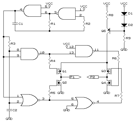
Following is a "Pool Algae Eliminator" using simple but effective electro-chemistry. Overwiew The following circuit uses two copper rods that are slowly eaten away by a combination of the electricity forced through them and a low dose of acid used as an electrolyte. Unfortunately one cannot just simply put two copper rods into the water, put some current through them, hoping they will now eat away. The rods will start to "plate" and soon develop an insulating barrier and start acting like battery plates in a lead acid battery. To overcome this, the polarity on the two rods are inverted at a preset interval. The current is also limited through the rods so as to ensure no excessive current is drawn by the rods should the acid levels in the pool change. The rods are usually mounted inside the filter system of the pool but hanging the rods off the edge is also acceptable. Circuit Description R3 and C2 form a delay for the upper and lower complimentary pairs. As these devices turn off at a relatively slow rate it is important to ensure the complimenting transistor is off before turning the opposing one on. This delay circuit, together with the gates, does this function. Q5, D1 & 2, R8 & 9, form a constant current source limiting the current through the probes to approx 50mA. This can be adjusted but it must be noted that too high a level will cause sediment in the bottom of the pool. R4 to R7 limit the current from the logic gates to the gates of the MOSFETS as these have high gate capacitances. Also, the supply to the upper MOSFETS will not be at full potential and the resistors will limit the back current to the logic gates. An unregulated 12 volt power supply should prove adequate for this. Ensure that off load the voltage does not exceed 14 to 15 volts as this could damage the logic gates. It is suggested that it also be a totally isolated supply (no ground point) as the rods will be grounded in the pool automatically and serious ground loop currents could develop should the supply have a reference point to ground.
R1	270k
R2	560k
R3	270k
R4-R7	2k2
R8	12 ohms
R9	2k2

C1	47uF
C2	470nF

D1-D2	1N4148

Q1, Q3	any suitable P channel mosfet
Q2, Q4	any suitable N channel mosfet
Q5	any suitable PNP transistor
Please note the above circuit has not been tested and is for guidelines and experimentation only.
© 14.08.00 |
