|
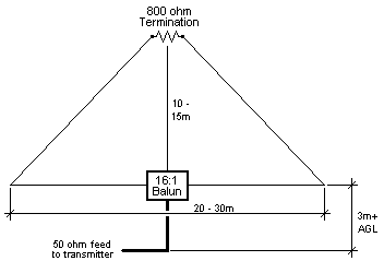
IT ALL BEGAN after I converted a old commercial rig using crystals into a continuously tunable one ranging from 1.6 to 25 Mhz. After telling a few about this I started to be approached by people asking if it were possible to monitor frequencies for them. This, I stated, was true but upon testing my dipoles found them to be very inefficient unless operated near their design frequency. This now 'general coverage' rig was missing one very important feature, an antenna that could match its capabilities! This presented a challenge. As everyone knows, any piece of wire can be an antenna but the SWR will leave much to be desired. OK, lets take a 50 ohm dummy load, attach a short (1m) piece of wire to it and we have an antenna with a superb SWR from dc to at least 50 Mhz but the efficiency still leaves a lot to be desired. AFTER DIVING INTO THE BOOKS it was decided to try the T2FD as per diagrams supplied in many articles but I have yet to find out how they get an SWR of better than 2:1 across the range, I never got below 3:1. Back to the books. Moxon had the answer that ALL antennas of this nature work with, the characteristic impedance of the wire! If the wire is terminated with this impedance the standing wave disappears and a travelling wave is set up. THE NEXT ATTEMPT yielded results sought, an antenna with an SWR of better than 2:1 from 1.6 to 25 Mhz. What was used was a 16:1 balun atop a mast with the antenna legs stretched across the property corners and the ends terminated to ground via 400 ohm resistors. I had the Irene transmitter site just down the road which assists in testing antennas. Hey presto, only a small degradation in performance, but I was to get a rude awakening! The low angle pattern of this antenna was great ie. DX here we come but local was dead. Again, back to the books and there it was, the travelling wave starts from the source, moves towards the load and continues in the same direction. What I was doing was shoving all the energy into the ground! What was needed was to 'invert' the source and load so that the wave 'travels' from down to up (ie. towards the ionosphere). What would work would be an antenna that was fed at the corners and terminated at the top (this in itself would have been a feat). Instead, it was decided was to try a delta sitting on its base terminated at the apex. This was tried straight away with 800 ohms termination as this represented the closest to the wire's characteristic impedance (I also had the balun ready) and again, less than 2:1 SWR across the entire HF band. Tests have proved that this antenna is a little lower in efficiency than a dipole as long as the wire length is equal or greater than one wavelength at the working frequency. The efficiency drops at frequencies lower than this 'cutoff' but not to the detriment of the SWR which remains constant. All that happens is the resistors get a little warm!
I have managed two successful constructions, the first being 4 x 2-turn windings on a 2-hole bead intended for use in an HF final, the second as 4 x 2-turn windings on a host of small ferrite cores (making up a larger 2-hole bead). I don't know what the material was as these all came from stripping down smashed HF rigs. Asking around local hams should yeild results.
73's, Marc.
© 30.03.03 |
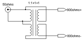 The balun poses a little bit of a challenge. Firstly, there are very few schematics for this beast. It is nothing more than a 1:4 voltage (equating to a 1:16 impedance) wideband transformer. The construction is a 'quadfilar' winding (4 windings placed over/with each other) on a suitable ferrite material.