|
A question asked of many who have complained about a system showing signs of not being too healthy and there is a strong suspicion the antenna system is at fault. But, when pressed for an answer the usual one is "No" followed by the 'reason' being "the antenna is out of reach". Before we get too entrenched in the belief that a 'good SWR' makes a good antenna think about a 50 ohm resistor. It will show a perfect 'SWR' yet be the most inefficient antenna. There are certain antenna designs that can exhibit a perfect 50 ohm match yet act as a RF sponge radiating very little of the energy injected into them. Standing Wave Ratio (SWR) is the ratio of the peaks and troughs of current & voltage that appear on the coax as a result of any mismatch at either end. It is generally accepted that transceivers operate at the correct impedance (typically 50 ohms) so any SWR will be as a result of connector or antenna imperfections. In the past SWR was actually measured on a piece of 'open coax' and thereby determining mismatch. Modern techniques measure the mismatch with the aid of a RF bridge and accept this to be the SWR. However, this move has brought with it pitfalls which will be highlighted below. RF engineers generally accept that SWR values of up to 1.5:1 are acceptable in any antenna system. Yes, it's not ideal but also very little is lost with such ratios and only represents 4% reflected power. The problem is that with long runs of coax there is no way of knowing the true condition of the antenna without measuring the match (or mismatch) of the antenna itself.
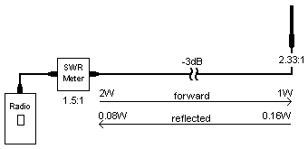
The antenna system consisted of an end-fed dipole on a 10m stayed tubular mast (which is why no-one wanted to pull it down), the feed was 15 metres RG214 coax. The input power was 2 watts and SWR measured 1.5:1. What was required was to prove, beyond doubt, the antenna system needed an overhaul. To start with all the figures need to be calculated. The coax length represented 3dB loss at 460 MHz. The SWR of 1.5:1 = 4% reflected = 80mW. However, this 80mW is what was measured at the radio and has already suffered 3dB attenuation in the coax which puts the real reflected power at 160mW. Furthermore, this was reflected from an antenna that was fed from 2W less 3dB i.e. 1W. Therefore the real SWR was

This did not convince the client that his mast should come down but when done and the calculated SWR happened to be a fraction better than the actual (2.5:1) even the technician was convinced that a new antenna was called for. Calculating the "modified" SWR is a simple three-stage process and is outlined below. The first stage calculates a ratio from the coax loss expressed in dB. The second stage calculates the voltage ratio of forward to reflected of the measured SWR and multiplies this by the loss factor thus increasing the resulting SWR. The third stage then takes the new voltage ratio and reverts this back to SWR.
Let's close with another very real situation involving a repeating system using a 430MHz up-link and 465MHz broadcast system. The link used a Yagi and the broadcast used a 4-stack dipole. The system, since being moved to a new site, performed poorly and the site was blamed for many months. Again the SWR was measured repeatedly and found to be about 1.4:1 at all times on the broadcast system and about 1.7:1 on the link. As the link path was very strong no attention was ever paid to the SWR on the link until careful thought was given to the situation. Again the antenna system required special machinery to lower the mast and was only done after the following calculation was made. The coax runs on both antennas was 25m, the link being RG213 and the broadcast ½-inch heliax. The coax loss was approximately 4.8dB = loss factor of 3.0. The measured SWR was 1.7:1 which means a Vr of 0.27. When multiplied by the loss factor of 3.0 we have a new Vr of 0.81. This then translates into a revised SWR of approximately 9.5:1. When the mast was finally lowered it was found an inexperienced technician had wired the wrong antenna to the wrong cable. The Yagi had fooled the situation all along as it was unfortunately assumed the Yagi would have shown a terrible SWR if used on the wrong frequency - it didn't (the reason why may well lie in the next section!). These calculations should prove emphatically that SWR measured at the radio must never be trusted in sites where there is a long run of coax.
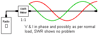
As said above, when a coax is terminated with an impedance other than its characteristic impedance a standing wave forms along its length. This happens as the construction of a coax is effectively a string of ¼-wave cavities back-to-back. Voltage and current curves, 90° out of phase from one another, will exist as pictured below.
What becomes apparent is that the voltage and current curves cross over each other at ½-wave intervals. Using the argument that Z = V/I, there are points that V & I could be such that they represent an impedance (Z) close to the characteristic impedance of the coax and therefore the antenna system. Should the coax be cut at or about this point and a SWR meter connected, the reading could well fool someone into believing all is well with the antenna system. As a general rule when testing antenna systems either during commissioning or fault finding comms problems, the tests should be conducted as normal and then with a ¼-wave length of coax added into the antenna line. A large difference in readings between the normal and extended coax indicates that coax resonance is hiding a potential short or open circuit.
Creating a ¼-wave line is not always the easiest, especially at higher frequencies as the coax could be very short but any odd multiple of ¼-wavelength is permitted (although it is suggested that it be limited to 1¼-wavelengths). The formula for calculating a ¼-wavelength section is L = 49.5 / f where L is in metres and f in MHz. This is for all solid dielectric coax cables (it does not have to be exact and this is close enough for practical purposes). | | Ask a Question | 14.01.01 |
 Measuring Antenna System SWR
