|

 Wiring Analogues as Digitals
Analogue Input as Digital Input
With MODBUS now being a well established standard, most systems follow suit and relay most, if not all internal information using a 16-bit format. With MODBUS the ON state is when the value is equal to or above 32768 and OFF when 0 to 32767. If the analogue input on the device in question uses the 16-bit word to convey the analogue level such that the mid voltage/current range (e.g. 12 mA on a 4-20mA signal) equals 32768 or 8000H, then using the analogue as a digital input merely becomes a matter of ensuring there is sufficient current through the analogue input when ON is desired, and conversely, significantly low current to equal the OFF state.
In the following examples it is assumed that the analogue input reads 4-20mA with 12mA being represented by a value of 32768 (8000H). To test if the input will satisfy this requirement inject 4mA into the input and read the output value (in our example it was very near 16384 or 4000H) and then inject 20mA and read the value (in our example this was very near 49152 or C000H). This gives the span as used by the input, in our case 4-20mA was spanned over 8000H counts, centred around 8000H - in other words, perfect.
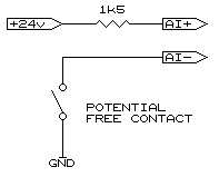
 In order to ensure the input exceeds 32768 (8000H) it is advised to use 16mA rather than rely on 12mA as any small errors will make the input unreliable. Using Ohm's Law (V ÷ I = R) we can determine the value of the resistor. In our example we used the supply voltage of 24 volts therefore 24 ÷ 0.016 = 1500 (or otherwise known as 1.5k). It must be borne in mind that the maximum of 20mA must also not be exceeded and this minimum resistance is again calculated with Ohm's Law and in our example 24 ÷ 0.02 = 1200, (or 1.2k). In order to ensure the input exceeds 32768 (8000H) it is advised to use 16mA rather than rely on 12mA as any small errors will make the input unreliable. Using Ohm's Law (V ÷ I = R) we can determine the value of the resistor. In our example we used the supply voltage of 24 volts therefore 24 ÷ 0.016 = 1500 (or otherwise known as 1.5k). It must be borne in mind that the maximum of 20mA must also not be exceeded and this minimum resistance is again calculated with Ohm's Law and in our example 24 ÷ 0.02 = 1200, (or 1.2k).
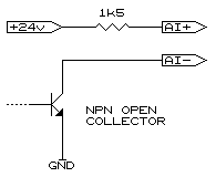
 The same method can be adopted when using open collector outputs as indicated in the accompanying diagram. The only criteria is to ensure the output is able to sink the whole 20mA with some capacity spare so as to ensure long working life of the output. It will be noticed in both the above examples that the current limiting resistor is placed between the +24V supply and the high (+) input to the analogue channel, with the low (-) input being used as the equivalent digital input. This is done for safety in that should the line from the input be brought to earth no damage is done to the analogue channel. If the resistor were in between the low (-) input and the contact and a short to ground occurred ahead of the resistor the full potential of the supply would be found across the analogue channel which would damage it. The same method can be adopted when using open collector outputs as indicated in the accompanying diagram. The only criteria is to ensure the output is able to sink the whole 20mA with some capacity spare so as to ensure long working life of the output. It will be noticed in both the above examples that the current limiting resistor is placed between the +24V supply and the high (+) input to the analogue channel, with the low (-) input being used as the equivalent digital input. This is done for safety in that should the line from the input be brought to earth no damage is done to the analogue channel. If the resistor were in between the low (-) input and the contact and a short to ground occurred ahead of the resistor the full potential of the supply would be found across the analogue channel which would damage it.
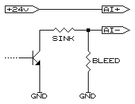
 Certain outputs, especially older solid state types, may not be able to sink this level of current, however, all is not lost. Reducing the current the output has to carry is done by using a "bleed" resistor which then carries some of the current. We will assume, for the sake of an example, our output is not allowed to sink more than 10mA. We want to draw 16mA to safely assume the value transferred is high enough so we need the bleed resistor to draw the remaining 6mA the output is not allowed to carry, therefore, 24 ÷ 0.006 = 4000 (or 4k). Such a value is not available but 3.9k is and this is then used. To calculate the sink resistor to draw 10mA, 24 ÷ 0.01 = 2400 (or 2.4k). In the above example the 6mA drawn through the analogue input by the bleed resistor when the output is off is low enough to ensure the value is well below the transition value of 32768 (8000H). Certain outputs, especially older solid state types, may not be able to sink this level of current, however, all is not lost. Reducing the current the output has to carry is done by using a "bleed" resistor which then carries some of the current. We will assume, for the sake of an example, our output is not allowed to sink more than 10mA. We want to draw 16mA to safely assume the value transferred is high enough so we need the bleed resistor to draw the remaining 6mA the output is not allowed to carry, therefore, 24 ÷ 0.006 = 4000 (or 4k). Such a value is not available but 3.9k is and this is then used. To calculate the sink resistor to draw 10mA, 24 ÷ 0.01 = 2400 (or 2.4k). In the above example the 6mA drawn through the analogue input by the bleed resistor when the output is off is low enough to ensure the value is well below the transition value of 32768 (8000H).
Analogue Output as Digital Output
Analogue outputs are not that easy to interface to digital inputs but with a little trickery they can, in most cases, be successfully interconnected.
Some outputs work from 0-20mA making interfacing extremely easy while others only operate from 4-20mA, the lowest current being more than most digital inputs require. A further problem is some analogue outputs are 'alarmed'. If the full current is not being drawn it could force them to either shut down or bombard the controlling system with a continuous warning.
As most digital inputs are optically isolated interfacing is simply achieved using a resistor across the input on a 0-20mA circuit, the value being:
(VAo - 5) ÷ (.02 - IDi)
where:
VAo = Voltage feeding the analogue loop and
IDi the current taken by the digital input.
The reason the voltage is reduced by 5 volts is the current regulating circuit within the analogue output requires a little voltage for everything to work. The full 20mA is reduced by the portion of current fed through the digital input. In our example we will assume an analogue loop feed voltage of 24 volts and a digital input current of 3mA and the result would therefore be 19 ÷ 0.17 = 1118 ohms. Always use the next lowest common value resistor, in this case 1000 ohms (this ensures the analogue output will not alarm).
If the analogue output is a 4-20mA type, or the digital inputs are fed from separate voltage rails, an additional diode and zener diode are required. We will require the voltages of both the digital input rail and the analogue loop feed in order to complete the calculations. In our next example our digital input system uses 12 volts on the opto-isolator, it draws the same 3mA, and the analogue is fed from 24 volts.
Calculating the resistor is done using using the same formula as above. Where things change is we now need to calculate the voltage swing across the resistor relative to the digital input. This is achieved by first calculating the 'off' and 'on' voltage levels:
Voff = 24 - (.004 X R) and in our case = 20V
Von = 24 - ((.02 - IDi) X R) and is = 7V
The swing is VDi - Voff to VDi - Von and. in our example, is -8v to +5. The first value also determines the zener diode value, but in this example the value being negative indicates we don't require a zener diode and may be removed from the circuit.
As they say, "simple when you know how".
|
| Ask a Question |
03.11.00
|
 Wiring Analogues as Digitals
 In order to ensure the input exceeds 32768 (8000H) it is advised to use 16mA rather than rely on 12mA as any small errors will make the input unreliable. Using Ohm's Law (V ÷ I = R) we can determine the value of the resistor. In our example we used the supply voltage of 24 volts therefore 24 ÷ 0.016 = 1500 (or otherwise known as 1.5k). It must be borne in mind that the maximum of 20mA must also not be exceeded and this minimum resistance is again calculated with Ohm's Law and in our example 24 ÷ 0.02 = 1200, (or 1.2k).
 The same method can be adopted when using open collector outputs as indicated in the accompanying diagram. The only criteria is to ensure the output is able to sink the whole 20mA with some capacity spare so as to ensure long working life of the output. It will be noticed in both the above examples that the current limiting resistor is placed between the +24V supply and the high (+) input to the analogue channel, with the low (-) input being used as the equivalent digital input. This is done for safety in that should the line from the input be brought to earth no damage is done to the analogue channel. If the resistor were in between the low (-) input and the contact and a short to ground occurred ahead of the resistor the full potential of the supply would be found across the analogue channel which would damage it.
 Certain outputs, especially older solid state types, may not be able to sink this level of current, however, all is not lost. Reducing the current the output has to carry is done by using a "bleed" resistor which then carries some of the current. We will assume, for the sake of an example, our output is not allowed to sink more than 10mA. We want to draw 16mA to safely assume the value transferred is high enough so we need the bleed resistor to draw the remaining 6mA the output is not allowed to carry, therefore, 24 ÷ 0.006 = 4000 (or 4k). Such a value is not available but 3.9k is and this is then used. To calculate the sink resistor to draw 10mA, 24 ÷ 0.01 = 2400 (or 2.4k). In the above example the 6mA drawn through the analogue input by the bleed resistor when the output is off is low enough to ensure the value is well below the transition value of 32768 (8000H).