|
Here we investigate more deeply the relationship of voltage and current, and the effect the one has on the other. In most power quality issues many people look to the voltage to ascertain the fault. One should rather investigate how the current reacted to the change in voltage, being especially careful not to discount changes in the current causing voltage fluctuations. Having just the voltage recorded will do nothing more than indicate the average voltage and that you have had a sag, swell, or impulse (of course, this may be your only concern). Seeing how the current reacts will allow you to ascertain whether the fault was beyond the test point, or before it.
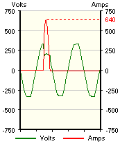
A perfect example of this is shown alongside (captured during the tracing of intermittent trips - the fault being an intermittent short). The current shoots up at the same time as the voltage falls. The phase of the current vs. the voltage indicates the short being 'downstream' of the test point (energy is 'imported'). When the fault is ahead of the test point the opposite reaction is true with current usually following the voltage trend. What is also significant is the current will have a delayed reaction with the delay being anything from milliseconds to many cycles, the latter especially true of installations where motors form a major portion of the load. One word of caution; be careful of motor current curves with respect to voltage. The current draw of a motor rises significantly immediately following a sag. Semi-complex recorders may lead you to believe that there was a fault beyond the test point when in fact it was before. Interpretting this type of fault is covered in the section on Min, Average, and Max. This rule is broken when dealing with switched input rectifier systems, as found on some modern UPSs. The first component after the rectifiers is usually a battery bank capable of delivering many amps. If the synchronising circuit driving the input switches should develop a timing problem then the battery could be forced to feed back onto the incoming supply. "Feed Impedance" concentrated on the effect a varying load had on the input voltage. But the relationship continues further as it is not just the individual load that determines the voltage drop, but the sum of the loads as a whole with an individual load being again affected by the total load structure. Let's simplify things. Let us use an example of a cooker element and an electric heater. Both are temperature controlled, the cooker using a standard bimetal strip temperature control, the electric heater an ambient air thermometer. The cooker element in this case is a low power (small) plate. When the heater is first turned on to heat the room, the effect is a large current draw (also because the heater will be turned onto maximum to get the room warm quickly). This causes the voltage to drop. At the same time a pot of water is put on to boil and to have it brought to boil quickly the control is set to max. The room arrives at temperature, the thermostat clicks out and the voltage goes up a few volts. The cooker plate can now deliver more heat and suddenly the pot is boiling over (with the one who was watching the pot now getting very upset!). Although the above example was on a micro user scale, the same thing can happen on a macro scale as well. 24-hour industrial plants have been known to suffer during night hours when the total load is down i.e. the incoming voltage is way up. This is especially true when the plant is rurally situated and the regulation not as well administered as in urban areas. As shown, the current (if small enough) may not in itself affect the voltage, but can in itself be affected by the voltage. It is this within this relationship we now investigate two manifestations being the uneven distribution of voltage and/or current (called imbalance), and a method of determining the direction of a fault, but first, what is meant by Feed Impedance.
© 02.04.04 |
 INTERPRETING THE READINGS:
 When the fault is beyond the test point the current will react instantaneously to the voltage with the current and voltage having opposing characteristics (current rises while voltage falls, and vice versa).