|
Before I even start this section, there is one primary rule that must be obeyed; If you are not prepared to do this properly, If this is you, then get someone in who is prepared to use the correct kit, and to then connect it up as they should. Right, with that out of the way... I covered the basics behind nuisance trips here. On this page I cover methods for capturing the reasons of nuisance and intermittent trips. Yes, the two are different! The Definition Revisited: Intermittent trips are circuit breakers rightfully operating because of an unknown cause or fault. Nuisance trips are a breaker deeming a non-existent fault has occurred and, in so doing, operates without need. Even though intermittent trips and nuisance trips are completely different in nature, dealing with the problem is fortuitously tackled in exactly the same manner. To start with; Of absolute must is having the correct kit for the job. All too often I hear of people trying to trace issues with inferior or inadequate kit (no, a current clamp and a multimeter, or a clamp-on ammeter, is not going to do the job!). And, saving a bit of cash hiring inadequate kit will soon get used up with time spent on site (and 'cowboys' do that!). When done properly, only one recording is required as it will show why the breaker is tripping. As the common factor in both scenarios is a trip, first establishing if the fault is intermittent or nuisance and then tracing the cause is pure inefficiency. Doing it "all-in-one" saves time and makes you look good with the customer. The better piece of kit for this job is a Power Quality Digital Storage Oscilloscope type device. 'Full Disclosure' recorders tend to be more "voltage triggered" devices and could miss the reason behind the fault (except, by following the rules below, I have successfully used both in tracing both intermittent and nuisance trips). Also, my experience is PQ-DSOs allow all the traces to be superimposed on one another and thus give quicker results. The Rules:
I just want to pick up on one point made in two of the above rules - 'Using suitable clamps'. All too often I see inexperienced individuals trying to use large current clamps on small earth-leakage trip problems. It defies common sense to use a 100A clamp or larger to accurately assist in determining imbalance currents of 15mA. If using a PQ-DSO, adjust the MIN/MAX triggers on the voltage channels to CBEMA values. Set incoming current channel MIN at 0% and MAX at 80% of the circuit breaker trip current. For the earth-leakage (Live-Neutral imbalance) channel, set the MIN to 0% and MAX at 50% of the RCD (ELCB) trip current. You're set. Now all one has to do is... WAIT !
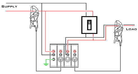
The above is the correct set-up for determining intermittent/nuisance trips. The connections are to a Dranetz 658. The incoming supply current is monitored with a 100A clamp and the Live-Neutral imbalance is measured with a 1A clamp.
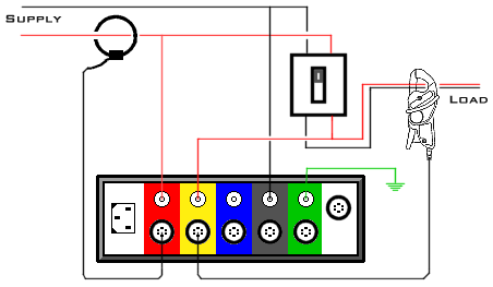
Above is a very successful set-up of a Reliable Power Meters Power Recorder for determining intermittent/nuisance trips. The recorder is set to "split single phase". Please note the incoming supply current is monitored with a 100A 'flexi', and the Live-Neutral imbalance is measured with a 5A (maximum) clamp.
© 28.09.04 |
 MEASUREMENT TECHNIQUES:
