|
Testing power factor correction capacitors is often done incorrectly. It is not uncommon to hear of multimeters capable of measuring capacitance being used to determine if a power factor correction cap is fully functional. There is one basic component missing from the test being the operating voltage. The multimeter may be able to determine the capacitance, as well as the leakage, but all this testing is done at a mere few volts - a far cry from the 230V or so the capacitor is asked to work at. Also, power factor correction capacitors are now often required (by certain electrical codes) to have "bleed" (discharging) resistors across their terminals. Such resistors play havoc with multimeters having the capacitor appear to have far higher capacitance than printed on the side. Finally - using your multimeter is one sure way of not showing any respect for your trusted friend. Such capacitors are prone to holding charge especially if they were disconnected at the peak of the cycle - and don't believe the "bleed" will discharge as personal experience shows most burn out after prolonged use! Placing the multimeter across the charged cap can damage it beyond repair.
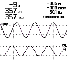
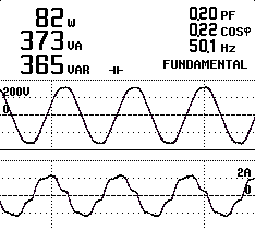
So true tests require the proper kit - but it is not a complex piece of kit. Any half-decent power quality analyzer is all that is needed. The tests rely on the fact the capacitor is used to correct power factor by introducing the correct number of VARs on the system. As pure capacitance will introduce perfect VARs, the test is simply to measure if the VARs being introduced is pure. This is done with the aid of the Power Factor measurement screen. I use my trusty Fluke 43B. Here are screenshots of such power factor correction capacitors. It will be noticed on the good cap, the power factor is very close to zero, and the VARs (if calculated back) equals the capacitance printed on the can (20µF).
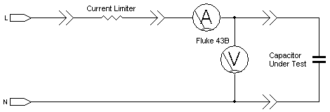
Faulty capacitors tend to be extremely "leaky" - almost as if a resistance, far lower than the "bleed" resistor, is across the capacitor. This is noticed by the angular displacement being far less than 90° (the actual watts showing the energy absorbed by the capacitor, which translates into nothing short of heat!). Another failure is "break-down" when subjected to working voltage. Testing for break-down requires a little time and is tested using the instrument's transient capture feature. The capacitor has a natural transient suppression characteristic so mains borne transients seldom affect this test (so captured transients typically emanate from within the capacitor). If the capacitors are in circuit, and nothing appears faulty (especially nothing is overly warm), then connect the PQ analyzer to the power factor correction as shown in the diagram below (ignoring the 'current limiting resistor' for now). Testing suspect capacitors out of circuit is best done with an extra level of safety. I use a very simple form of current limiting (as featured here). This will allow the capacitor to be subjected to close to working voltage, yet limit any current should the capacitor decide to finally go short circuit.
The analyzer is set to record long term VARs to ensure the capacitance does not vary much, as well as recording transients - the latter being a quick indication the capacitor is breaking down internally. A note: When testing suspect capacitors, please enclose them in some protective casing as faulty capacitors are known to literally "blow their tops" and spew their insides all over the testing area (and the oil in oil-filled types has a very unpleasant odour that lasts for weeks!).
© 11.11.05 |
 MEASUREMENT TECHNIQUES:

