|
"Power Factor Correction - In essence, using inductors is not an issue apart from the inherent characteristic - the current flowing through them lags the voltage injected. This causes the current to go up with "no return on investment" as shown in the section on "artificial consumption". What was also shown is how 'power factor' is the relationship of volt-amps and true energy usage expressed in watts. The only real danger is the consumption meter turns a little quicker, and wires may get a little warm owing to undue currents being conducted. To correct this, items known as "power factor correction capacitors" are used as the means to fool the supply into believing that the load is resistive. Using power factor correction does not have a direct impact on power quality per se. Please make a serious note of this. I have seen far too many people call themselves power quality businesses when they actually do nothing more than reduce losses and therefore make the usage meter spin a little slower. Yes, agreed, there are times when implementing such power factor correction can cause further complications, and it is this we deal with now. What we will not deal with is power factor correction as such - not because we don't understand it, but because it does not fall within the boundaries of power quality. Basically these capacitors are designed to operate at the fundamental of 50 or 60Hz. The harmonic content is usually only a few percent of the fundamental but with larger capacitors a surprising amount of energy may be absorbed by them. The formula that will give the power absorbed at the specified harmonic of 50Hz is:
At first this may not appear excessive, until one compares this against the fundamental current. Our 20µF capacitor has a current flow of 1.51A meaning the extraneous current of 0.46A has increased the total by an extra 30% to 1.97A. At the 3rd and 5th harmonic this may still appear somewhat under control, but try recalculating this when adding 1.5% distortion at the 11th and 13th harmonic as a result of a 12-pulse input inverter! A suggested method is to take all harmonics (minimum of odd orders from 3rd to 63rd) and calculate the sum of the current of all harmonics (for ease, base this on 1µF). Divide this by the fundamental current and you are now left with a ratio by which the wiring and any other components need to be overrated in order to handle the currents involved. When subjecting a standard fluorescent lamp to an average medium business' power supply it was calculated the capacitor would be forced to conduct roughly twice as much current. Physical tests confirmed this.
The PFCs shown alongside were not so lucky. These capacitors were already pushing the limits with regard ratings. The voltage they were used at was the rating on the capacitor (one always over-rates the voltage), and they were supposedly 'self-healing' except the self-healing characteristic is exacerbated with heat. So, along came a little harmonic content and ... (the rest, as they say, is history). Suppliers/installers of power factor correction capacitors ignore harmonic content at their peril. A water pressure booster pump in a building filled with predominently hi-tech devices will, if installed correctly, have PFC attached. The motor itself has no harmonic content in its current curve, but that does not mean the PF capacitors are not conducting extraneous current well in excess of what they were designed for! And yet designers still strap PFC caps straight across the power... unfused!
© 04.04.04 | ||||||||||||||||
 CAUSES:
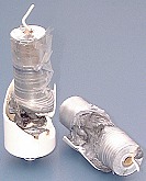 In our above example of a fluorescent light PF capacitor, the chances of it exploding through excessive current passing through it is slim as they can usually dissipate the energy absorbed (purely through their physical size). However, bigger capacitors should not be so easily dismissed!