|
"To make something stand still, One only has to ask a hard-of-hearing person who relies on using the 'T' setting on their hearing aid just how much 'buzzing' they experience to realize just how much a problem this is. Some hearing aids even switch automatically in the presence of alternating current magnetic fields if sufficiently strong enough. Yet, ask most folk involved with wiring why it is so important that each wire should be accompanied by a return and it can almost be guaranteed that the only return you'll get is a blank look! In simple terms, if current is flowing in a conductor, and there is not the same current in the opposite direction in a conductor placed directly alongside, then the conductor will radiate a magnetic field. Worse still, if the current is returned through a conductor placed some distance from the one being spoken of, then both conductors will radiate thus doubling the problem. The distance between the two conductors does not have to be much. 150mm would do it, but it usually a lot more than that. Although it is being written in to many regulations now prohibiting this practice, there are still many 2-way lamp circuits in existance where the switched wire is taken to the lamp directly from the 2nd switch instead of being fed back along the route between the two switches (thus cancelling any current) and then on to the lamp in question. Broken ring circuits are a prime culprit (loops being the most efficient radiators!), and it only takes one of the conductors, including Earth, to be broken and the problem exists. With the earth there is an extended problem as the Earth has all the EMC capacitors strapped to it and the higher frequencies are radiated with more efficiency (which is why the hearing impaired complain of 'buzzing' when subjected to these fields). Sometimes, broken rings are inadvertently created i.e. unintentionally. This can occur with relative ease with PME style systems where, in the hope of creating a suitable back-feed system, the Earths from two feeds emanating from one source are accidentally brought together forgetting the Earth is also the return path i.e. the Neutral. In such circumstances the radiated magnetic energy can reach astronomical proportions.
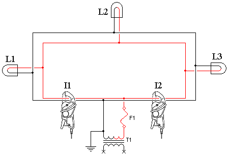
The advantage of a 'ring feed' is the ability for both continuous supply to a user should a break exist on any conductor, as well as raising the current capability of the feed to the user as there are two paths for the current to flow. Such 'rings' exist on a minor scale as plug circuits in most homes, and on a major scale in high voltage (HV) distribution networks. As an aside, ring feeds are not the same as 'back feed' systems where an arrangement exists for a user to be fed from an alternative source should the primary source fail. An example would be some switching/link arrangement allowing a user to be fed from Transformer B should Transformer A, or the feed from Transformer A, fail. A typical ring feed would appear as follows. For clarity, only a single phase feed is shown, but is as relevant for a 3-phase system.
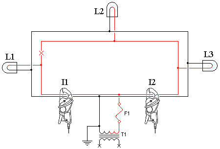
Ignoring the current clamps and the currents I1 and I2 for the moment; The current of load L1 will primarily exist, owing to the resistance of the cable being lower via that route, via fuse F1 and its associated Neutral. Similarly, the current of L3 will primarily be via F2 and its associated Neutral. The current of load L2 will be shared via both F1 and F2 and also both associated Neutrals. The sharing will be equal if the cable length and type is the same from the source (transformer) to load L2. If one were to assume the loads were placed at approximately one third, half way, and two thirds the way around the ring, the loads to be equal, and the ring to be made of the same resistance cable the whole route, then it would result in F1 carrying ²/3(L1) + ¹/2(L2) + ¹/3(L3) = 1¹/2(L). The same will occur with F2. Focusing now on the currents measured on the two current clamps, I1 and I2 (notice the Live/Phase as well as the associated Neutral is fed through the current clamp). No current will be shown at either of the two clamps as any current on the Live/Phase will be cancelled by an equal but opposite return current on the Neutral. In the following diagram, one Live/Phase leg is broken just beyond load L1.
In this scenario, the Live/Phase current of L1 is only found to appear at fuse F1 with none of the Live/Phase current appearing at F2. Similarly, all the Live/Phase currents of loads L2 & L3 appear at F2 with none of these currents appearing at F1. This results in F1 carrying all of L1 Live/Phase current with F2 carrying all of L2 and L3. The current distribution will now be F1 carrying 1(L1) + 0(L2) + 0(L3) = 1(L) while F2 carries 0(L1) + 1(L2) + 1(L3) = 2(L). However, all the associated Neutral currents still have the same distribution they had when the Live/Phase was not broken. This results in I1 and I2 each reflecting a difference of ½(L) (the only notable difference is the phase angle of I1 and I2 are 180º from each other). This situation is exacerbated by a break occurring in the opposite current carrying conductor (e.g. the Neutral in our example) on the opposite side of the loop. Should this occur, say, at just above L3, then the resulting currents measured at I1 and I2 would be 1(L) as at each point one conductor would be conducting the current of two loads while the other was only conducting the current of one load.
Identifying broken rings is usually through large magnetic radiation occurring within the ring. Hearing aid wearers who use the 'T' setting on their hearing aid are often the first to be affected by these, whether the broken ring is a minor scale or major scale. Hearing aid loops require approximately 100mA/metre of magnetic field for satisfactory use of the 'T' coils. To create a field of this intensity, a rule of thumb approach is it requires a current approximately a tenth that of the length of the side of a square loop (also accepted is the longest side of a rectangle). For example; A square loop of approximately 100m x 100m would require an uncancelled current of 10A in the conductor to create a field of 100mA/m in the centre of the loop. This intensity increases dramatically the closer one gets to the conductor forming the loop. Further identification can occur with the onset of CRT based television and computer monitor screens being "wavy" when subjected to the uncontrolled magnetic radiation from the broken ring. Measuring for uncancelled currents on the two feeds that forms the ring (as shown in the above diagrams) will confirm the existence of a broken ring.
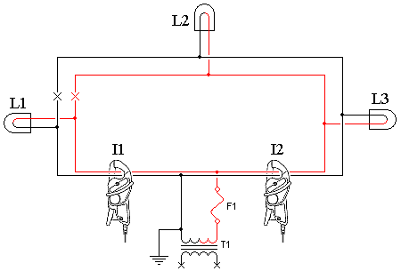
Curing a broken ring consists of one of two approaches. The first is to repair the ring. If this is not possible (through any reason, including planning etc.), then the second option is to break the all other current carrying conductors at the same place the broken conductor exists (shown in the picture below).
Although this is the explanation as to why there is a need to ensure currents are cancelled, I don't think that it will entice many to use magnetic field testers (as used for hearing aid loops) to ascertain the health of and electrical installation! Reliance on Problem Solving Software >>
© 30.04.03 |
 CAUSES:

