|
"Power Factor Correction - There is an interesting issue with regards harmonic content and PFC capacitors being the energy such capacitors have to transfer when subjected to harmonic content. Basically these capacitors are designed to operate at the fundamental of 50 or 60Hz. The harmonic content is usually only a few percent of the fundamental, but with larger capacitors a surprising amount of energy can be absorbed by them. I've had folk argue with me on this one saying the capacitors do not absorb energy as the cap, having a power factor of zero, simply imports the energy on one portion of the cycle, and then exports it during the next portion - all this occurs regardless of the frequency. This may be true, but... The import and export process occurs within the dielectric and is not 100% efficient causing the capacitor to retain some of the energy during the process, then ridding itself of the energy in the form of heat. And the higher the frequency, the less efficient the process! Although the power dissipated within the capacitor (its dielectric) might be minimal, what must also be borne in mind is this extraneous current flows through the capacitor's dielectric which has a finite peak current carrying ability, and any heat lowers this value. Not only is the current carrying ability reduced through heat, but also the breakdown voltage of the dielectric. THD calculations can not be used here! I have seen literature that uses the THD value transposed into a "derate" factor (KF). This does not calculate the absolute peak current flowing through the capacitors dielectric. Good power quality analysers show the total odd and even harmonic content as well as THD - but capacitors need a different total value! If the current across the capacitor is not available, or you have to plan for a capacitor being installed, then by using the harmonic breakdown (Fourier's principle) of the input voltage and the following formula the additional peak current across the capacitor at 50Hz is simply:
At first this may not appear excessive, until one compares this against the fundamental current. Our 20µF capacitor has a fundamental current flow of 1.51A (2.14A peak) meaning the extraneous current of 0.46A has increased the total by an extra 30% to 1.97A (2.8A peak). At the 3rd and 5th harmonic this may still appear somewhat under control, but try recalculating this when adding 1.5% distortion at the 11th and 13th harmonic as a result of a 12-pulse input inverter! When subjecting a standard fluorescent lamp to the harmonic content found on the average medium business' electrical distribution, it was calculated the PFC capacitor would be forced to conduct roughly twice as much current. Physical tests confirmed this.
The fact capacitors will be found to have 'ropey' current waveforms when strapped across power systems with harmonic content, has led to the unfortunate teaching claiming capacitors "amplify" harmonics on electrical distribution systems. This is just not true! Capacitors will, however, naturally shunt any harmonic content present on the electrical system. In doing so, they will intensify the high-frequency current on the electrical distribution system between the capacitor and non-linear load. This means installing power factor correction may lead to the need to increase the ratings of electrical switchboards to cope with the increased high-frequency current!
The PFC caps shown alongside were not so lucky. These capacitors were already pushing the limits with regard ratings. The voltage they were used at was the rating on the capacitor (one always over-rates the voltage - see below), and they were supposedly 'self-healing' except the self-healing characteristic is exacerbated with heat. So, along came a little harmonic content and ... (the rest, as they say, is history). There is sufficient proof too that skin effect occurs within capacitors meaning the higher frequency conduction occurs more at the edges rather than the centre of the plates forming the capacitor. This is partly true as some of the conduction also occurs at imperfections in the plates. These cause a 'gathering' of electrons (the imperfection simulating an edge of a plate) making breakdown possible not only on the edges of the plates, but also within the capacitor. Suppliers/installers of power factor correction capacitors ignore harmonic content at their peril. A water pressure booster pump in a building filled with predominantly hi-tech devices will, if installed correctly, have PFC attached. The motor itself has little harmonic content in its current curve, but that does not mean the PFC capacitors are not conducting extraneous current well in excess of what they were designed for! It, therefore, comes as no surprise these capacitors fail with almost monotonous regularity as the imported energy can go nowhere else but be converted into heat; And heat breaks down the dielectric and thus reduces the working voltage limit (if not just simply distorting the plates causing short-circuits). And yet designers still strap PFC caps straight across the power... unfused!
A suggested method is to take all harmonics (minimum of odd orders from 3rd to 63rd) and calculate the sum of the current of all harmonics (for ease, base this on 1µF). Divide this by the fundamental current and you are now left with a ratio by which the capacitor needs to be overrated in order to handle the currents involved. Power factor correction capacitors come with a kVAR rating. Once calculated what the added peak current is, such as 70% in the example shown in the screenshot, then simply increase the kVAR rating of the intended capacitor. This is done by using a capacitor whose working voltage is higher, but leaving the required capacitance (µF) value the same. In this example a 60µF cap was strapped across 430V i.e. 1.11kVAR. Increasing this by 70% brings us to 1.89kVAR. A 60µF cap rated at 560V will work perfectly (the next standard voltage being 630V making this even more resilient!). Watch out too for so-called 'dry' types. These are extremely prone to breaking down when subjected to both voltage and current transients (the latter from dirty switch contacts and switch-on inrush). Always consider oil-filled types. Apart from being just a lot more resilient, the oil allows the can fixing (if fixed to metal) to be used as a heatsink thus keeping the capacitor a little cooler. And their resilience pays off in a very short time! When Inductors and Capacitors 'Marry' >>
© 04.04.04 / 24.03.05 | ||||||||
 CAUSES:
 The screenshot alongside shows a rather nasty current waveform through a PFC capacitor. Using the above formula showed this capacitor was conducting up to 70% extra current; The actual tests confirmed this too.
 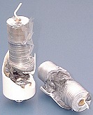 In our above example of a fluorescent light PFC capacitor, the chances of it exploding through excessive current passing through it is slim as they can usually dissipate any additional energy being absorbed (purely through their physical size). However, bigger capacitors should not be so easily dismissed!