|
A capacitor corrects the power factor of an inductor by having a current curve complementary to the curve of the inductance being corrected. The only means by which this can occur is to have characteristics opposite to that of the inductor. One characteristic I want to pick up on is the inductors' frequency dependent "resistance". If opposite to an inductor, then a capacitor must have a negative frequency dependent "resistance" (again, I know it should be referred to as "impedance" and more so "reactance", but stay with me!). As the inductor's characteristic is the higher the frequency, the higher the "resistance", the capacitor's characteristic is the higher the frequency, the lower the "resistance". Therefore, opposite to the inductor that will tend to retain a sinusoidal current curve in the face of a distorted applied voltage, the capacitor exacerbates any high-frequency component (distortion) of the curve to a relatively high degree!
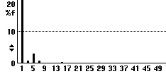
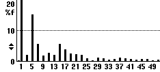
Above are waveforms and harmonic spectrums of a simple power factor correction capacitor (captured with the aid of a trusty Fluke 43B). The voltage waveform is only slightly flat-topped, but notice what this has done to the capacitor waveform! Revisiting the definition of a linear load, wherein it is stated that the current curve of a linear load is a direct replica of the voltage curve (even ignoring any phase angle), has thus proven a capacitor is not a linear load. I'm sure there are a few folk out there thinking their power factor corrected motors are linear loads. Until now that is. Neither the motor nor the PFC caps are proven to be anywhere near linear. They're probably mortified by this!
"They have been around Although Marconi first experimented with radio using a spark generator, it is no longer the fashionable method of transmitting information. Nowadays it is usually nothing more than simply annoyingly conveying to the listener that something has turned on or off. As the capacitor's characteristic is a lower "resistance" with a higher frequency, and switching noise is nothing more than high frequencies, means the capacitor can be employed to "short out" the noise. So in steps the first reason the smaller capacitors were used - spark quenching. These are usually little more than a few nF strapped across a set of contacts (usually in series with a small resistor to stop contact burn) and the spark is much reduced, and so is the interference on the wireless too! What was also noticed by these earlier engineers is that transients too were reduced. Seeing as a transient was reduced by a cap across a set of contacts, it also made sense they could stop possible spikes making their way into a piece of equipment if used across the power carrying conductors and Earth. But in so doing they are not ridding the system of noise, just ensuring it bypasses the equipment and goes straight to the Earth. It must not be forgotten then noise has mainly a high-frequency component and, again, the higher the frequency the more the capacitor will conduct it from the Live and Neutral to the awaiting Earth. There is another problem; Do this on every piece of equipment and you're no longer living with merely a few nF strapped across the current carrying conductors and Earth, but a few µF. This whole aspect is covered in more detail later in "Leakage in Technology", but suffice to say that it is not just power factor correction capacitors that cause a load to be non-linear, but all the EMC capacitors in use today. Furthermore, this non-linear load is not only being strapped across the Live and Neutral, but a relative portion of it is being strapped between Live and Earth - as if the earthing structure needs it!
© 15.10.04 |
 CAUSES:


