|
This is another way of talking about 'Power Factor'. Before we start, it must be said that power factor is not directly related to power quality. The only relationship is the meter may spin a little faster than it should and therefore assumed (incorrectly) the power is 'bad'. The reason it is included is to show why this happens and how it is cured. As is, power factor correction can create power quality issues (this is covered later). With resistive loads, the voltage and current curves are perfectly in phase meaning the peaks occur at the same time. This is the most efficient transfer of energy from the source to the load. However, this is an imperfect world and not all loads are resistive. In fact, most loads have some form of inductive or capacitive component which is why consumption is quoted in VA. However, this does not indicate the actual, or perceived consumption. In steps the term 'VAr', or volt-amps-reactive. In the event you did not read all the definitions, this is the consumption that will be indicated by typical consumption measuring devices as a result of phase angles between voltage and current. But is this really an issue? Does it really matter if the current curve is away from the voltage one. Hopefully the following indicates the effect.
In our case, when summing the imported and exported power, the load's curve works out at a mean of 70% and thus truly represents the energy being used by the load. Modern instrumentation (which multiplies the instantaneous voltage and current) will arrive at the same result, but older instrumentation will simply multiply the RMS voltage and RMS current and arrive at a figure some 40% higher. This latter figure is known as "apparent power". A further complication is the fact that although the apparent power is e.g. 1kW the actual output power from the motor is only 700W (assuming the motor is 100% efficient). Should we require a genuine 1kW delivered by the motor the current would have to be increased by the same 40%.
First things first. The capacitor current always leads at 90º (shown in thick blue). If the correct amount of current (chosen by the size of capacitor) is then superimposed on the lagging current of the load, the result is a current curve equal to 70% of the current of our example load. If this is then multiplied with the feed voltage the power curve is also 70%. But this is exactly what the original summed power curve worked out to be, is it not? Yes, it is but the important fact here is that it is now in phase with the voltage meaning any power consumption metering equipment will read the true power taken by the load. Also, any losses that were associated with the higher currents with no PF correction are reduced. Now ain't that smart! What is amazing in all of this is the fact the power curve of the capacitor (thick brown) would comfortably have one believe that no power is taken as the curve shows power being both imported and exported in equal quantities. A bit of something for nothing? Not quite, but it's close!
It is a myth to think motors, transformers, and other inductive loads run any differently or more efficiently just because a power factor correction capacitor is strapped across (have a look around, it is amazing how much literature says a power factor correction capacitor improves motor efficiency!). It was indicated that a load with a non-unity power factor will export the unused energy back to the source, but this is not done with 100% efficiency. So not only will the consumption meter turn a little quicker, the mechanism in the meter might view the energy as 'in phase' and cause the meter to spin quicker in any event. I am not disputing that higher currents causes higher losses, but am saying the losses are confined to the distribution system (everything used to bring the juice to the load). The difference power factor correction makes is the current in the distribution system is lowered, and is also brought in phase with the voltage. This, therefore, reduces the losses in the distribution system. The current into the load (motor, etc.) remains unchanged! The reason electricity supplier (the clever ones, that is) fine a user with a non-unity power factor is the higher current on the cables makes the need for copper greater than it should be. With the above mentioned losses and the extra copper making a serious dent in their profits, they feel a need to recoup their costs from those who have caused it. By reducing the current by 30% (from 100 to 70%) does not mean the losses are reduced by 30%. Assuming the resistance of the distribution system remains relatively constant; Power is relative to I²R making the reduction in losses, in our example, a whopping 50%!
© 24.01.01 / 31.10.04 |
 SYMPTOMS:
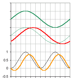 The graph shows the voltage (thick green), and resistive current curve (thin green) with the resultant power curve (thin black). It also shows the reactive current curve (thick red) of an inductive load with a power factor of 0.707 (45º). What will be noticed is the output curve (thick orange) is the same magnitude but is offset with respect to the resistive curve, together with the fact there are points on the cycle where the power appears to export from the load to the supply. This is not a mistake, this really does happen.
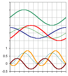 The next graph shows what happens when a capacitor of the correct amount is installed. I've never seen anyone ever show this in a graphical format (everyone always uses vectors - and most electrical people still don't understand how the power factor correction capacitor works!). We're not going to go into all the maths, there are enough companies wanting to sell PF correction units and willingly give away software that does it! We just want to ensure you're up to speed.