|

Remotely Accessing
Telog Recorders
TEXT BEING WRITTEN OVER TIME
There are times when remote accessing of a Telog recorder ('Telogers' or 'Linecorders') is either vital or prudent in time saving. 3 methods are available being remote RS232 devices (LAN based), PSTN (standard telephone line), and/or Radio (either radio modems or cellular technology). Remote access of Telog Linecorders, R-2000, and R-3000 series data loggers can be accomplished with these techniques.
When doing stubborn complaints the best option is to have the recorder set to the shortest recording interval and then analyse the data on a daily basis. However, this will result in a costly high number of visits to site. Having a fairly standard optically isolated RS232 port, these recorders almost beg connection to a modem whether a standard telephone, cellular, or radio type. The optical isolation creates a few challanges but these are usually of no concern with most modems.
We discuss all these methods below together with their advantages and disadvantages. We'll start with the most common and move through to the most uncommon.

The Required Signals:
There are only 4 pins on the Telog unit that need to be connected, these are shown below together with the pin numbers. The pin configuration is the "9-pin equivalent of the standard 25-pin".
| Tx - Pin 2: | Data transmitted from the Linecorder to the PC. |
| Rx - Pin 3: | Data recieved by the Linecorder from the PC, negative power for the interface is derived from this pin. |
| CTS - Pin 5: | Positive power supply for the interface port. |
| Ground - Pin 7: | Common point for all signals and must be connected to the interfacing modem as the port is fully isolated. |
On a hardware front, the modem should be RS232 compliant i.e. capable of delivering a minimum of ±8V into a standard load (4k7). This is required to power the optically isolated port. The modem to also have a working DCD pin (indicating successful connection).
Note: During all of the set-ups listed below, the speed of communications between the Linecorder and modem is set to 9600 Baud. Older documentation of Telog's will show modem speeds lower than this. Effectively, this is a waste of on-line time especially in the light of the fact that modern modem technology is more than capable of this. When communicating locally with a Linecorder, ensure the data rate is 9600 Baud else the recorder will not work with the modem when installed in the field.
Programming and Testing the modem:
There are many "cheap and nasty" modems on the market and you would do well to steer clear of them. The modems featured here have been tested and proven. Should you not have these available, then a set of tests should be carried out on the modem to ensure it will work.
There are effectively only two operational requirements with regards the modem. The first is the modem should be completely "silent" when not on-line to another modem, the second is that the DCD pin be programmed to show when a connection is extablished.
The following are typical commands required to place the modem in a state suitable for working with the Telog units. Parameters shown in parenthesis (xx) are what has been found to be common amongst a number of modems.
| AT&F | Factory Defaults | Always start off with this command. This ensures the modem is in a known state. Some modems (the M20 and 405U included) will default to factory default communication speeds and require that you change the baud rate of the terminal package to that default speed. |
| AT&Cn | DCD indicates modem connected | Where 'n' is the number required to have the DCD pin indicate the presence of a succesful connection. Please consult the modem manual for the correct value. |
| AT&Dn | ignore DTR | Where 'n' is the number required to have the modem not require the DTR signal. Some modems, if not programmed to ignore this line, will not go online if this signal is not supplied. Please consult the modem manual for the correct value. |
AT?
(&K0) | ignore RTS | The commmand to have the modem to not require the RTS signal. Some modems, if not programmed to ignore this line, will not send data. Please consult the modem manual for the correct value. |
AT?
(+MS) | Set modem connection baud rate. | This command (see the modem's manual) will set the connection speed for the modem. This needs to be limited (preferably fixed) to 9600 Baud for the Telog units. This forces the modem that dials in to limit its speed. Not all modems offer this facility and may depend on the following command to limit the speed. |
AT?
($SB) | Set modem serial baud rate. | This command (see the modem's manual) will fix the serial port speed. This needs to be fixed to 9600 Baud for the Telog units. This may also force the modem that dials in to limit its speed. Not all modems offer this facility, however, the serial baud rate is usually held in an 'S' register (common is S23). The same register usually holds a few other pieces of vital information and is stored as a whole with the AT&W command. |
| AT? | set hardware | Back to the manuals on this one. Some modems (such as the M20 and 405U) need to have special commands issued to set up the hardware specifically for this purpose. Such commands are covered in the sections below. |
| ATM0 | turn off speaker | Not a vital requirement, but usually modems that 'squawk' attract the attention of prying fingers. Experience has shown that modems that operate quietly usually continue working, unhindered! |
| ATE0 | turn off echo | Ensure any data sent by the Telog unit is not echoed back to itself, especially when idle (disconnected). No characters are echoed from this point on. |
| ATQ1 | stop any responses | This setting stops the typical "OK" from being displayed as well as any other 'status' reports and error messages should the modem disconnect and the Telog unit is still transmitting. The modem will no longer show a response to any entered commands. |
| AT&W | save these settings | This command should save the settings to a non-volatile RAM and be the settings used when the modem is powered-up. Please type carefully as there is no echo to see any mistakes and no response to show any error. |
PSTN (standard telephone line)
Public Switched Telephone Networks (i.e. standard telephone lines) are probably the most common method of accessing a remote location. Most sites have telephone lines available to both the user and recorder. The advantages are almost immediate access (if the line is installed) as well as a fairly reliable yet relatively inexpensive connection.
PSTN lines are not suitable for situations where none exist as the installation costs are usually prohibitively expensive. In such situations, refer to the section on Radio.
The diagram below shows the inter-connections between a Modem and a Telog Recorder ('Telogers' or 'Linecorders').
Personally, the only recommended range of modems is "MultiTech". Below is the set-up instructions for model MT5600ZD when used with a Telog recorder. Programming is done by connecting the modem to a PC and using any reasonable terminal program to send the commands to the modem. Note: The "enter" key must be pressed after entering each line as shown below.
Command Issued: | - Instruction carried out: |
| at&F | - Default to Factory Settings |
| at&C1&D0&K0 | - Carrier Detect Operational
- DTR Disabled
- Flow Control Disabled |
| atM0 | - Mute speaker (cuts noise) |
| atS0=2 | - Answer in two rings |
| at+MS=9,1,9600,9600 | - Set Modem Data speed to 9600 baud |
| at$SB9600 | - Set Serial Data speed to 9600 baud
Note: This command only for 'ZDX' models. |
| atE0Q1 | - Echo off
- No responses
Note: Nothing is seen on the screen from this point on |
| at&W | - Save the settings |
Radio
Radio comes in two 'flavours', either direct radio modem links or dial up versions being cellular phone technology. The advantage of the latter is the ability for 'analogue' modems (standard telephone types) to access the cell networks if technologies such as GSM are used.
GSM
 The Siemens M20T and MC35i have proven a most reliable form of "dial-up radio modems". The Siemens M20T and MC35i have proven a most reliable form of "dial-up radio modems".
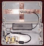
A suggested layout is shown alongside with the M20T built into a rugged box with an IEC320 mains connector on one side, and a 9 pin D type connector on the other (mimicking the socket on the modem itself). This facilitates the modem being kept some distance from the recorder which could otherwise be affected with strong 900MHz signals.
Below is the diagram to interconnect a Telog recorder to the Siemens M20T and MC35i.
Siemens M20T
Programming the M20T is relatively simple, but care must be exercised when issuing commands to the M20T. These are listed in the table below. Please note that the recorder is not asked to do anything strange with the M20T other than to dial. The reason for this is the baud rate modifies when issued with an AT&F command to 19200 baud. Also, it complicates testing if the SIM PIN or PUK is invoked. It will be noticed these are disabled in the M20T.
There are only a few things to be careful of. Once having obtained the SIM and accompanying number, you must also obtain a "data number" (this is a number the PC modem must dial to have the analogue modem signals converted into GSM data). The best method found is a "pay-as-you-go" number with data number (yes, there are such SIMs available) so that should the SIM be stolen, it is effectively useless after a few phone calls. Other contracts available are "receive only" or "limited calls" again to protect the SIM from running up an account.
Command Issued: | - Instruction carried out: |
| at&F | - Default to Factory Settings
Note: From this point the M20T is operating on 19200 baud. |
| at+IPR=9600 | - Change data rate to 9600 Baud
Note: From this point the M20T is operating on 9600 baud. |
| at+IFC=0,0 | - Flow Control Disabled |
| at&C1&D0&S1 | - Carrier Detect Operational
- DTR Disabled
- DSR shows 'data' mode active |
| atS0=2 | - Answer in two rings |
| atE0Q1 | - Echo off
- No responses
Note: Nothing is seen on the screen from this point on |
| at&W | - Save the settings |
Siemens MC35i
Programming the MC35i is even more simple than its older brother. Also, it complicates testing if the SIM PIN or PUK is invoked. These must be disabled before placing the SIM card in the MC35i.
Command Issued: | - Instruction carried out: |
| at&F | - Default to Factory Settings
Note: From this point the M20T is operating on 19200 baud. |
| at+IPR=9600 | - Change data rate to 9600 Baud
Note: From this point the M20T is operating on 9600 baud. |
| at+IFC=0,0 | - Flow Control Disabled |
| at&C1&D0&S1 | - Carrier Detect Operational
- DTR Disabled
- DSR shows 'data' mode active |
| atS0=2 | - Answer in two rings |
| atE0Q1 | - Echo off
- No responses
Note: Nothing is seen on the screen from this point on |
| at&W | - Save the settings |
If there are any questions please ask.
This web page does not form part of any official documentation.
Any information contained herein is used at own risk.
© M.T.P. - Marc's Technical Pages 22.08.02
|