|
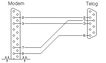
The diagram below shows the inter-connections between a PC and a Telog Linecorder.
In most cases, dispensing with the resistors and connecting Pin 5 of the PC directly to Pin 7 of the Telog will work. However, it has been known for many notebooks to not have Pin 5 (signal ground) connected. R1 and R2 provide an "alternative ground" arrangement for this situation yet limit any ground loop currents that may exist should both Pin 5 and the case be connected within the PC. A full explanation regarding this can be found here. R1, R2 - 10 to 22 ohms, ¼watt resistor. P1 - DB9 female connector P2 - DB9 male connector If there are any questions please email © M.T.P. - 18.07.01 |