|
The Power Recorder lends itself superbly to ascertaining domestic and industrial nuisance tripping issues.
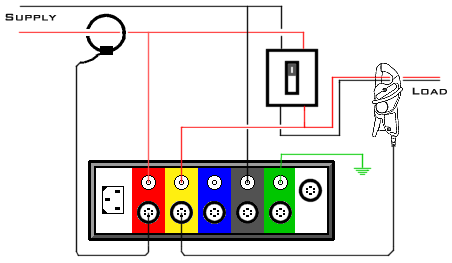
Switch the Recorder into "Split Single Phase". Connect 'A' to the Live before the Earth Leakage Breaker / Residual Current Device (it is also strongly suggested that the recorder have its power derived from before the breaker too). Connect 'N' to Neutral before the ELB/RCD. Connect 'B' to the Live after the ELB/RCD. Use a suitable current clamp for the load and clamp/wrap this around the Live conductor only (either before or after the breaker, it makes no difference). Plug this into Channel 'A' current input. This is a critical step (and, no matter how many times this is requested, it appears to be ignored). Take a 5A clamp (the newer "parrot jaw" style is better) and clamp this over both the Live and Neutral conductors. Failure to do so will result in the leakage current not being measured. Plug this into Channel 'B' current input. Hint: Use cable ties to bring the Live and Neutral conductors close enough together to not have them prise the jaw of the 5A clamp open. Determining the extent of the tripping is easily done using the event and trend screens. During a trip, an event will be recorded on Channel B as the voltage will change by more than the 2% required to cause a trigger. The event's current waveform will show the imbalance (leakage) experienced by the ELB/RCD during the trip. Channel 'A' will have a matching event if it is the mains supply that is influencing a trip. No matching event will indicate that the load is the likely cause of the trip. The voltage and current trends become useful if there is a changing leakage current from e.g. water ingress in a cable etc. that is leading to the nuisance tripping.
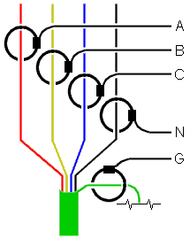
During an analysis of a site, it is known fairly common for only 4 CTs to be installed, this being one around each phase and one around the Neutral. This can lead to issues when leakage currents are at play.
The intended method of setting up a recorder is to wrap a CT around each phase, one around Neutral, and one around Earth. The problem with this is the Earth may not be isolated from true Ground (terra firma) meaning current could still flow back to the supply, but not via the earthing network provided. The following is based on the fact that all currents that flow from the Live(s) should return on the Neutral. Those that don't are leaking to Earth, regardless of the path.
If the problem is nuisance tripping, then a further improvement is to swap the N and G current inputs (leave the voltage inputs as normal). The G input does not have all the harmonic analysis performed on it (the N does), which can be useful if earth leakage breakers are proving more sensitive at higher frequencies. Having the Neutral plugged into the G input allows for at least the Neutral RMS current to be logged. The placing of the 'G' CT is important. It is suggested that this be placed where the four main conductors are in close proximity to each other e.g. where they leave a cable (but ensuring the Earth is separated out). Experience has shown a satisfactory combination of CTs is the primary ones to suit the load, and one 10% of this for the Earth currents (e.g. four x 1000A and one x 100A). Industry appears to have recommended that one should never see higher than 0.5% of total current drawn (but this is not a hard and fast rule!). However, if full current earth faults are being, or suspected to be experienced then one must step up to a full range CT for Ground currents.
Note: This web page does not form part of any official documentation. © M.T.P. - 08.01.03 |
 Although the RPM Power Analysis Software has the ability to "summate" the various currents and thereby determine leakage currents, it can only do this in real time mode or with initial oscilloscope readings. Also, CTs have error. This can lead to either a false sense of low leakage, or an exaggerated current that may not actually exist. It has been found that Rogowski coils ('Flexi') can have as high as 3% error from various factors such as nearby metallic objects.
 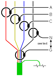 This preferred method is to have the main CTs again round each conductor (R, Y, B, & N), but the G wrapped around all four (R-Y-B-N). Should a current not return on the Neutral it will not cancel out the respective phase and will therefore be picked up by the Ground CT. This method also resembles the Earth Leakage Breaker (RCD).