|
Uninterruptable Power Supplies (UPSs) are being used in many situations where power critical systems are installed. However, contrary to popular belief, UPSs are by no means perfect and are often the reason behind equipment malfunction or, worse still, failure. The Reliable Power Meters' range of recorders are fitted with 4 voltage and 5 current channels i.e. designed to monitor all aspects on a single through to 3-phase star power source. If the UPS is single phase input and output and has a common Neutral, then the instrument is simply set to "split phase" for this purpose. When the UPS is a combination of multi to single, single to multi, or multi-multi phase, then things start getting interesting! The common solution provided by most instrument suppliers is to sell the client two recorders, one for the input and one for the output. However, this solution, although things are kept 'standard', does have a few distinct drawbacks. It is relatively costly. It involves multiple communications systems (LANs and hubs). It does not provide a very good method to analyse cross-UPS events (two separate recordings that then need to be synchronised). And last, but not least, there are more than likely unused channels. If we analyse the criteria that would spark off an investigation it would be the output from the UPS has exceeded some predefined limit, usually voltage or frequency. If the output voltage remains stable then interest in the input voltage is nothing more than seeking reassurance that the UPS is shielding the load from the rough outside world (careful, trap approaching!). The standard UPS configuration appears to be 3-phase in, single phase out. In this mode the easiest approach is to use the proven "4th channel method". In this mode the N-G channel monitors the output channel while channels A, B, & C monitor the input. The only restrictions are, even if a delta supply, the input must be monitored in star mode - this restriction will apply throughout this paper - and the output Neutral is commoned to Ground, although this is fait accompli with good UPSs. While on the subject of single phase output UPSs, there are many instances when the output is not grounded but left floating. This is becoming common practice in data centres as it allows for a line-ground fault on either of the two output lines (as well as saving energy by reducing leakage). The system may raise an alarm, but will not trip. The same is done on ships with the added measure of hopefully preventing fires. In situations such as the above, an isolation transformer will need to be used to maintain the integrity of the floating system. Care will need to be exercised in the choice of transformer taking issues such as flash-over voltage into account. If harmonics are an issue then very careful product research will need to be carried out. The solution presented here utilises some of the Power Recorder's current channels as voltage channels by presenting a voltage to the current input via a suitable attenuator. The ratio is 500:1 making the input range of these new inputs 1000VACrms, although it is not recommended that such voltages be measured without VTs. The inputs are wired up with the standard voltage inputs measuring the UPS output, and the new inputs measuring the UPS input. Should a voltage disturbance occur on the UPS output then an event is captured with the secondary (current) trace showing any disturbance on the input, and whether this was cause of the output disturbance - all this without the need to synchronise recordings from two separate recorders!
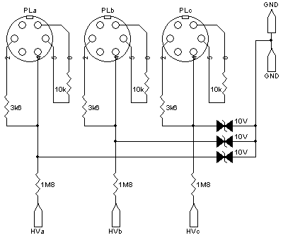
The input resistor (1.8M) is a Caddock MG740 (min) range part with a breakdown of over 5kV (the recorder we're interfacing to is rather precious!). The lower leg resistor (3.6K) is a 1W device to ensure it never goes open. The tranzorb ensures the output never exceeds 10V, which happens if the channel is disconnected. Please ensure the ground wire is connected before any work begins. The 10k makes the input current scales indicate 1A for 1V input (making the substitution simply amps=volts). Apart from the usual fact that almost every facet of the various inputs are measured, there are some interesting by-products. The most interesting is the power factor graphs. This usually measures the angle between voltage and current (sorry to state the obvious), but now indicates the phase-lock angle between input and output and can therefore track the power factor correction mechanism of the UPS control circuitry. If it is suspected the input and/or output current is playing a part in the UPS malfunction, then there are two channels still available for measuring current. In both cases the current clamps are installed in "phase subtractive" mode (the one phase is reversed). Although not ideal, it does indicate (to some extent) if there has been a current issue. If load imbalance is suspected (3-phase output UPSs are susceptible to this) then the clamp is simply installed around all three phases in the normal additive mode (3-phases, if balanced, when summed equal zero). Should the output not be balanced the level of imbalance will be indicated through this channel. It is recommended that RPM's Scenario software be used for this application as it allows for comparative analysis of various measurements e.g. input voltage to output voltage, on one graph. This solution is also usable on an External CT version MultiPoint for fixed locations, but not usable on either the Insite or standard version MultiPoint as there is no means to inject a voltage into the current channels. In both cases it involves far too much modification and is prohibitively expensive. If work practices permit, there are methods of converting standard current channels into voltage channels as shown in this document. If there are any questions please ask. Note: This web page does not form part of any official documentation. © M.T.P. - 29.10.02 |
