|
Although not perfect, the following method allows a user of the RPM-PR to take readings from a delta-star VT yet correct the phase angles to allow a reasonable accuracy of power factor values. Please note that this method shifts the related voltages and currents away from each other and any voltage events will not have the correct current waveforms associated with that event. The difference between two phases (e.g. A & B) is 120°. If this is summed with the delta-star shift of 60° we land up with 180°. So, by clamping the current clamp to the correct CT secondary, and then inverting it to correct the 180° phase angle, we land up with a relatively simple method of combatting the problem (as long as we accept the conditions mentioned above).
If a large Vn-g voltage exists this may be as a result of a grounded phase on the VT secondary (some call it "two watt-meter method"). This is discussed in the page entitled Measuring when the reference is not 0V.
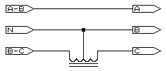
As can be seen, the winding N to A-B represents the input as found between phases A & B. All that is required is to retrieve phase C. The winding N to B-C is used after the polarity of the output from this winding is inverted.
A transformer with two equal voltage windings is required (a small mains isolation transformer is ideal) with each winding capable of the voltage from the star transformer. This is configured as an 'auto-transformer' as shown in the diagram and wired up as as follows:
As this method works with "subtractive vector techniques" to derive the voltage between the C and A inputs, higher order harmonics may be incorrect by a small degree although this is usually small enough to not be concerned about it. It will also be noticed that only two windings from the VT are used making this an ideal solution for systems where two single phase VTs are installed (otherwise known as 'open leg'). If there are any questions please email NOTE: This webpage does not form part of any official documentation. © M.T.P. - 30.11.01 |
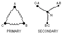
 Many measurement VTs are Delta-Star configuration (as shown alongside) resulting in 60° phase shift in the measurement voltages relative to current. This shift plays havoc with power factor figures. However, correcting this is merely a matter of inverting one phase from the VT and using the correct input mode on the instrument.