Elpro Wind-Solar Repeater Site
![]()
Elpro Wind-Solar Repeater Site
Elpro radio telemetry units are also store and forward devices and therefore make excellent repeaters within an Elpro radio telemetry system. In some instances the system requires a repeater atop a mountain in order to have the signals relayed across the required area. Mountain tops normally lack two very important requirements, power and accessibility.
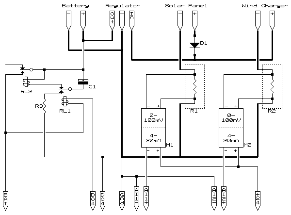
Power can be achieved by the use of solar, wind, or a combination of both. These are easily implemented as can be seen in the circuit diagram below. With a few added parts all the site data can be relayed to a suitable station within the system so as to collect statistical data and trends for both future planning and predictive maintenance.
Although unlikely, inadvertent "lock-ups" can occur with accessibility then becoming a major issue especially if all that is required is a power-down power-up cycle (total failures cannot be remotely repaired). A simple hardware watchdog has been built into the circuit below comprising of two relays, a resistor and a capacitor.

The principle of operation of the above circuit is the currents of each individual charge source is measured across the two 10milli-ohm 4 pole current sense resistors into two 0-100mV signal conditioner modules converting this into a standard 4-20mA process signal relating to 0-10A charge.
These devices were specifically chosen as they are two-wire (loop powered) 4-20mA transmitters with 0-100mV input and fully galvanically isolated. This allows the normal Elpro loop supply to power these without the need for special power supplies or, as they run on 24 volts, the need to ensure they can run on low voltage loops (typically +12V). It will be noticed the current sense resistors are in the negative leads, this is to ensure the common mode voltage is within an acceptable range should the transmitter chosen not be an isolating type e.g. a bridge input type with 0-100mV sensitivity.
Note: The Negative (-) connection from both the solar panel and wind charger must not be brought to earth other than through the current measurement resistors. If the negative is in anyway earthed at the device it will affect the current readings. A seperate earthing system bonding all the cases/shells of the various components must be implemented and not made to carry any current so as to avoid corrosion and false readings.
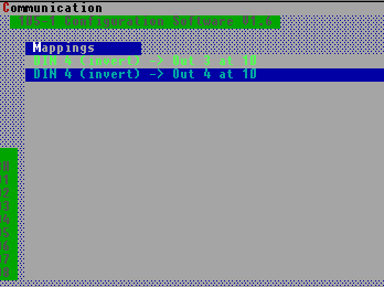
The remainder of the circuit (to the left) is the repeater watch-dog circuit. This circuit works in conjunction with carefully programmed parameters set within the unit. Using the Elpro 105U-1 (set as Unit 10 in our example) the required mapping, as shown below, uses an unused input (DI4 inverted) mapped to DO4. DO4 will therefore become active shortly after power-up. Not shown, but also programmed into the system, are the mappings of two remote units who also keep this output activated.

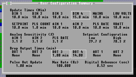
The timings used are important. The remote units (keeping the output updated) are programmed for 5 minute updates with the local mapping updating only every 15 minutes. The output is programmed to reset on a "no comms" at 14 minutes.

The logic is:
The output is made active shortly after power-up by the local mapping. This will energise relay RL1 which will switch the capacitor across the supply via the current limiting resistor.
The remote mappings ensure the output stays active by updating within 5 minutes. Two remote units are used to ensure that a re-cycle does not happen should one of the remote units fail.
Upon no receipt of any updates (comms fail through e.g. receiver lock-up) the output drops, this being possible as it will time-out (14 minutes) before the next local update (15 minutes). Relay RL1 will drop out and switch the capacitor across the power interrupting relay RL2 which will remain energised for the time it takes the capacitor to discharge across the relay.
Should the unit also not start receiving within 14 minutes after a power re-cycle the unit will automatically attempt another re-cycle to clear the problem. If a re-cycle is desired by maintenance staff, although there may be no fault, a simple reset instruction sent from one of the units that update DO4 will force such a re-cycle.
The system can be developed a little further by connecting DO3 to DI1. DO3 is programmed to reset on comms fail at 1 minute and DI1 is programmed as a pulse input. With the timings shown the pulse can now be relayed to a host station as a "number of successive 15 minute intervals before recycling" count and relayed to the host as a handy maintenance indicator. A re-cycle, as discussed in the previous paragraph, would reset the pulse count if desired.
Further to this DO2 can be programmed to become active on a comms failure of any nature, if then tied to DI2 this can then relay to a suitable station that there has been a comms problem. Persistance of this alarm (triggering many times during a short period) would point to a station requiring maintenance.
Although the repeater watchdog could be more elegantly achieved with eletronics the circuit was designed with simplicity in mind and for assembly by those with basic electrical wiring skills.
R1, 2 = 10milli-ohm 4 pole current sense resistors
R3 = 100 ohm ½-watt
C1 = 2200µF @ 25V
D1 = suitable Solar Panel blocking diode
M1, 2 = 0-100mV to 4-20mA loop-powered signal conditioning modules (e.g. Newport type 504)
RL1, 2 = miniture SPDT 12Vcoil e.g. LZ12 (coil > 390 ohms)
If there are any questions please email
© 14.08.00