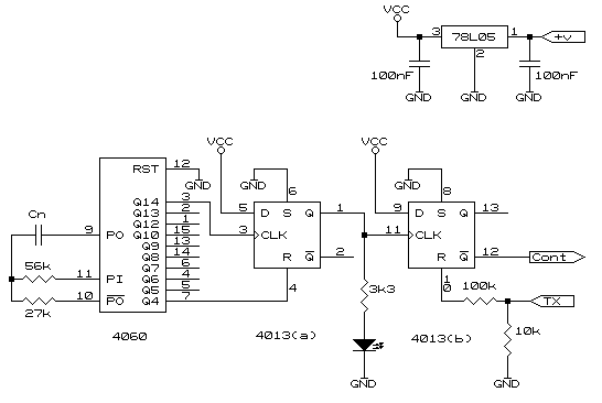
Overview With the aid of the circuit shown below the DGH module can, with the CONT pin, send a conversion at a time interval required.
Circuit Description The LED is used to indicate a trigger has happened and remains on until Q4 goes high. Should the LED remain on for too short a time pin 4 of the 4013 can be alternatively connected to any of the remaining outputs (Q5..Q13) of the 4060. The second flip-flop will remain on until there is transmission from the DGH module. The module requires that the CONT pin is held low until there is transmission. If an indication is required that the DGH is transmitting, a LED in series with a 3k3 resistor could be wired between pin 13 of the 4013 and GND. Timing If there are any questions please email NOTE: This webpage does not form part of any official documentation.Any information contained herein is used at own risk. © M.T.P. - 20.07.01 |
